Hi guys, some good news.
I managed to get the TDA1541A output voltage to 0 using the circuit QSerraTico_Tico recommended. Thanks Quirck.
I played some music through it and there is clearly an issue with the grounding. Where does the return go from the output of the Cen? Not to the DAC ground? I have the Output of the Cen directly driving my F5, so far looks like it may be enough gain for my speakers with the IV resistor at ~2.5k.
Cant obviously give listening impressions yet but my first impression was... huge bass compared to my last output stage, as SRPP tube circuit.
Any advice on the grounding issue welcome.
Ryan
SRPP? The attached schem doesen't show such a circuit......huge bass compared to my last output stage, as SRPP tube circuit.
Hmm.. not the feedback i was expecting.
Read it again carefully. I said my last output stage.
Maybe i should have been more specific.
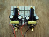
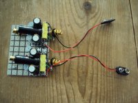
In the second photo i posted, i used only part on the circuit, the first part right after the I out of the DAC. The current bias...
At the moment i have 0V on the output of the DAC, and i'm just wondering whether the distortion im getting may disappear if i increase the voltage within 25mV (as per DAC compliance).
Grounding still an issue i think.
The typo may have confused you, sorry.
Should have been "a SRPP "
Read it again carefully. I said my last output stage.
Maybe i should have been more specific.
In the second photo i posted, i used only part on the circuit, the first part right after the I out of the DAC. The current bias...
At the moment i have 0V on the output of the DAC, and i'm just wondering whether the distortion im getting may disappear if i increase the voltage within 25mV (as per DAC compliance).
Grounding still an issue i think.
, as SRPP tube circuit.
The typo may have confused you, sorry.
Should have been "a SRPP "
Last edited:
Firstly if you use a +/-2mA (?) DAC with 2.5k Riv, you may consider using 24V floating supply instead of 18V.
Secondly, the current at the output of CEN goes through the Riv and then return to DAC Gnd.
And I do not understand why you say there is a grounding issue.
I presume you have not read the article. If so, please do. It was explained in detail.
It also helps others to help you if you post a schematics of what you have exactly built.
Patrick
Firstly if you use a +/-2mA (?) DAC with 2.5k Riv, you may consider using 24V floating supply instead of 18V.
Thanks for the advice, your right maybe i should use i higher supply for Cen. I'd just like to point out though, that i am not a professional. My inexperience will quite obviously shine through. So an explanation would be nice.
Secondly, the current at the output of CEN goes through the Riv and then return to DAC Gnd.
And I do not understand why you say there is a grounding issue.
Well let me elaborate. All i can say is that i came to this conclusion when i realized that moving certain returns gave different results, sometimes slightly better. Maybe i should have an output cap. Suggestions?
I presume you have not read the article. If so, please do. It was explained in detail.
It also helps others to help you if you post a schematics of what you have exactly built.
I have read the article, i understood a lot, but as i said, i am not a professional, so grasping everything on the first few reads has obviously not stuck. It will after a few more years of experience im sure of that. If i get time i will post a schematic. But i will say this: I used the original Cen circuit + a current bias circuit that injected 2mA to bring it to 0V at DAC out.
What would you recommend the IV resistor value be the 18v supply +-2mA swing?
Ryan
>All i can say is that i came to this conclusion when i realized that moving certain returns gave different results, sometimes slightly better.
> Maybe i should have an output cap. Suggestions?
I don't understand what you are trying to say, I am afraid.
What did you move, what changed, and what did you mean by better ?
Do you have a DC offset at the output ?
If not, then the output cap does nothing for you.
Did you connect the DAC Gnd also to your power amp or preamp ?
As I said, please post a schematics of what you have done.
All your description above did not make thing clearer, at least not for me ....
> I used the original Cen circuit + a current bias circuit that injected 2mA to bring it to 0V at DAC out.
But I have no idea what values of what component types you are using, and also what Idss in your JFETs, etc.
And what is now exactly the problem ?
Did you have oscillations ?
Do you have an oscilloscope (ideally up to 100Mhz) ?
> What would you recommend the IV resistor value be the 18v supply +-2mA swing?
1.4k
Patrick
I had some success getting rid of my grounding problems. Turns out if the battery cases are not grounded i get a crackling noise. And also i had an issue in my amp that i had to fix up.
Sorry i have no schematics, and no graphs to post as yet but if anyone is interested i will make the effort.
Patrick, as far as my 15Mhz scope can see, i have no oscillations even without the filter, my system seems stable.
Cant give listening impressions yet because i have very sub par parts, but bass seems very accurate compared to my SRPP output. Ill try a mobius loop resistor using CuNi44 wire for the IV conversion soon enough. Maybe tomorrow.
In my own experience there is no need to ground the battery cases.
It is likely you have some input output coupling.
You may try gate stopper resistors of say 100R for each FET.
And you should also trim the current source to zero the output DC.
The input will then be automatically zeroed.
Without a schematics, it is impossible to figure out what exactly the problem is from here.
But I salute you for the courage to experiment.
You are the only one so far to do a bread broad test.
Patrick
A question & please pardon my ignorance -
Is the value of the output impedance the same as the Riv? If so, a buffer on the o/p to reduce it would need another seperate supply with it's 0 volt tied to the dac's pin 5 gnd point, same as signal 0 volt on the o/p socket?
Perhaps this been covered before, but ......
Is the value of the output impedance the same as the Riv? If so, a buffer on the o/p to reduce it would need another seperate supply with it's 0 volt tied to the dac's pin 5 gnd point, same as signal 0 volt on the o/p socket?
Perhaps this been covered before, but ......
> Is the value of the output impedance the same as the Riv?
Yes. If you use an Riv at 2.2k or 1.4k, I consider that low enough to not warrant an additional buffer.
> If so, a buffer on the o/p to reduce it would need another separate supply with it's 0 volt tied to the dac's pin 5 gnd point, same as signal 0 volt on the o/p socket?
Yes. A buffer would need fixed rail supplies, separate from this circuit.
And if you wish to do that, then you may also consider using the buffer as a Sallen Key filter.
See also :
http://www.diyaudio.com/forums/digi...ng-new-ess-vout-dac-es9022-4.html#post2612326
> Perhaps this been covered before, but ......
Yes, in the discussion with Calvin about the Bipolar version of CEN.
As also mentioned, the bipolar version, as well as the current mirror version, has significantly more noise.
The original JFET SEN / CEN circuits are so quiet, that you hear absolutely nothing on a headphone with max volume.
The difference is not subtle.
This is all thanks to the separate current loop of bias and signal.
And the floating supply is a essential feature of that.
")
Patrick
.
Yes. If you use an Riv at 2.2k or 1.4k, I consider that low enough to not warrant an additional buffer.
> If so, a buffer on the o/p to reduce it would need another separate supply with it's 0 volt tied to the dac's pin 5 gnd point, same as signal 0 volt on the o/p socket?
Yes. A buffer would need fixed rail supplies, separate from this circuit.
And if you wish to do that, then you may also consider using the buffer as a Sallen Key filter.
See also :
http://www.diyaudio.com/forums/digi...ng-new-ess-vout-dac-es9022-4.html#post2612326
> Perhaps this been covered before, but ......
Yes, in the discussion with Calvin about the Bipolar version of CEN.
As also mentioned, the bipolar version, as well as the current mirror version, has significantly more noise.
The original JFET SEN / CEN circuits are so quiet, that you hear absolutely nothing on a headphone with max volume.
The difference is not subtle.
This is all thanks to the separate current loop of bias and signal.
And the floating supply is a essential feature of that.
Patrick
.
Last edited:
Thanks for the encouragement.In my own experience there is no need to ground the battery cases.
It is likely you have some input output coupling.
You may try gate stopper resistors of say 100R for each FET.
And you should also trim the current source to zero the output DC.
The input will then be automatically zeroed.
Without a schematics, it is impossible to figure out what exactly the problem is from here.
But I salute you for the courage to experiment.
You are the only one so far to do a bread broad test.
Patrick
I do have some dc offset in the output of one channel. Whats the best way around this, trimmers in series with the 560k resistors?
Ryan
> I'm wondering (as I'm ordering parts right now) if there would be any benefit to upgarde the 220uF Nichicon ES to something like MUNDORF or Blackgate NX or Elna BP/NP ?
Can you still get Elna NP ?
Can you get a reasonably sized Mundorf (MKP?) for 100uF, or even 22uF ?
I already explained in the article why the "distortion" (i.e. non linear V-I relationship) of the caps are unimportant, as long as current in = current out (Kirchoff's law). One of two profs asked me by PM why I did not simply use ordinary Eleytrolytics (and they will work just fine).
But if you want to try Blackgate NX, please do.
And come back and tell us whether you can hear a real difference.
I would probably try a 10uF MKS-2 one day. But it has no priority.
Patrick
- Home
- Source & Line
- Digital Line Level
- Zen -> Cen -> Sen, evolution of a minimalistic IV Converter