Member
Joined 2009
Paid Member
C1 connection is true or not? I want to try this ampSorry I screwed up the image upload, here it is.....
I can't see how this amp performs as claimed . You simply can't get 5 watts (or 15 watt peaks) with the mosfet running at 0.8A with an 8 ohm load. Defies physics or am I missing something ? Maybe this amp gives that 'chocolate sauce on everything' euphonic effect ? For a small amp I would have used a RD16HHF1 mosfet instead and run double the current through it with choke or CCS load . Much more efficient , more power , lower distortion and easier to get the feedback right ")
316A
316A
Hi Guys
The circuit in post-5 will likely have 700mV of DC offset. The base of the input transistor should not be ground referenced as shown, rather tied to a stable negative voltage that can be set for minimum output offset.
Similarly, the circuit in post-40 is likely to have high DC offset and be drifty. At the very least, an offset adjust pot should be added.
The single mosfet amp with resistive loading is a highly compromised one. Yes, it is simple and will not hurt speakers, but the gain is variable with the mosfet used. getting a stereo pair to be balanced could be tricky.
JLH showed the evolution of a class-A output stage from something similar, a BJT and resistive load, to a BJT with inductive load, to the final push-pull BJT form he used in his famous amp. As efficiency goes up from one form to the next, THD goes down. The single gain element circuit with no feedback will have wildly high THD, predominantly H2 but with all the rest just for laughs.
A safety resistor should be added from the centering pot wiper to ground - say 10M. If the wiper opens, the mosfet gate will be taken to ground and bias to zero.
If I am going to have something running as hot as any of these circuits, I want it to be super-low-THD. The advice to down-scale the circuit for headphones is the best here.
Have fun
Kevin O'Connor
The circuit in post-5 will likely have 700mV of DC offset. The base of the input transistor should not be ground referenced as shown, rather tied to a stable negative voltage that can be set for minimum output offset.
I see no schematic in post 5, did you mean post 11? That circuit has an offset of about 50mV because the current source sends some current down the feedback resistor to the output. The tempco of the current source closely matches that of the input transistor. The site that had the JLH articles, tcass.com seems to be gone.
I tried a similar circuit biasing the base of the input transistor to -.6V. Gave up because couldn't make it track supply voltage changes. The circuit in post 11 requires regulated rails. The things I've been working on lately are single rail with an output capacitor. I don't need rock solid lows or the problems to get them.
Similarly, the circuit in post-40 is likely to have high DC offset and be drifty. At the very least, an offset adjust pot should be added.
The pot on the MOSFET gate (scribbled note) effectively tweeks the offset. The mismatched resistors at the output introduce some nice H2 distortion. To linearize the circuit you actually need a larger mismatch as I documented in the ACA thread in the Pass forum. But lower distortion does not always equate to a better sounding amp and a more enjoyable listening experience.
The single gain element circuit with no feedback will have wildly high THD, predominantly H2 but with all the rest just for laughs....
If I am going to have something running as hot as any of these circuits, I want it to be super-low-THD. The advice to down-scale the circuit for headphones is the best here.
On the surface, an amp with distortion above 1% would seem to be unacceptable. I find them easy to listen to at low levels (<5W, mid 80's speakers, close range). The distortion makes them seem louder than they are. When a CD finishes playing, I want to play it again or put on another one. I listen to my ACA with the feedback disconnected. With no feedback, H4 and above are quite low.
Hi Guys
Loudthud, your point about listening to these high-THD amps "at low levels" deserves emphasis.
I find this to be a particular "problem" with such designs, that they only sound acceptable over a very small signal range. It is akin to the parameters and performance of tube gain stages, where mu, rp and gm are specified for small signal swings. Larger signals traverse more of the curved transfer function and distortion rises. The same happens with these high-THD designs. 1% may actually sound okay at 60db, but at 70db when THD has risen to 5% - even if it stayed at 1% - it would not sound as good as when quieter. At least for me, that kinds of performance are not what I want anymore. The novelty of building a working circuit such as the JLH was a few decades ago, now I have different standards and expectations - not necessarily better, just different.
Have fun
Kevin O'Connor
Hi. I posted a video featuring ZCA paired with Audio Nirvana Super 10 on modified Tannoy Autograph, reduced to 2:3 enclosures:
MINI AUTOGRAPH 2:3 replica with AUDIO NIRVANA SUPER10; bass horn modified. - YouTube
Music is played through an old DVD player and fed through a chip based resistor attenuator set to -30dB. As you can hear, there is no lack of power and dynamics.
In vivo the combination is magical and the amp is easy and cheap to build. I used -ECDesigns-' "charge transfer supply" with only two 10.000uF main caps, of which only the second one is "working" to supply the amp and the first can be a cheap one. PS is regulated with PowerReg from Teddy Pardo and gives around 20mV of ripple, so no humm and clean sound, IMHO.
Introducing the PowerReg - pink fish media
Dear Mark, I have some SIC power JFETs here but I can't design...would you mind adapting your ZCA to those? They say they sound "as triodes"...
Cheers,
M.
MINI AUTOGRAPH 2:3 replica with AUDIO NIRVANA SUPER10; bass horn modified. - YouTube
Music is played through an old DVD player and fed through a chip based resistor attenuator set to -30dB. As you can hear, there is no lack of power and dynamics.
In vivo the combination is magical and the amp is easy and cheap to build. I used -ECDesigns-' "charge transfer supply" with only two 10.000uF main caps, of which only the second one is "working" to supply the amp and the first can be a cheap one. PS is regulated with PowerReg from Teddy Pardo and gives around 20mV of ripple, so no humm and clean sound, IMHO.
Introducing the PowerReg - pink fish media
Dear Mark, I have some SIC power JFETs here but I can't design...would you mind adapting your ZCA to those?
They say they sound "as triodes"...Cheers,
M.
Maxlorenz: if your telling me that is a ZCA powering those speakers then I'm extremely impressed. How close to the original cct. Is it?
These days I'm caught up in many projects and unfortunately the ZCA re-make is not on the radar. I would like to make and further develop a MCA which I think may best the ZCA form an early prototype. Can we have a close-up image of your ZCA inside and out?
These days I'm caught up in many projects and unfortunately the ZCA re-make is not on the radar. I would like to make and further develop a MCA which I think may best the ZCA form an early prototype. Can we have a close-up image of your ZCA inside and out?
Member
Joined 2009
Paid Member
Dear Mark, I have some SIC power JFETs
For JFET look here: https://www.passdiy.com/project/amplifiers/zen-variations-9
Thanks Mark.
It is the ZCA indeed. The clue is good matching of components...
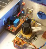
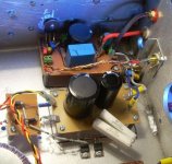
Here are pictures when it was clean:
Note "charge-transfer supply" only needs a few Schottky (or plain) diodes and a Mosfet, plus a a few resistors. To the right is the little PowerReg. This one has Siemens polyprop cap at output (//electro) but the other has now Russian NOS PETP, which is clearly better. I just had no time to upgrade. Since I have lots of them, I will probably exaggerate.
Can you see where the speaker cables are going?
Thanks dear Bigun. I'll try to analyze that...
It is the ZCA indeed.
The clue is good matching of components...Here are pictures when it was clean:
Note "charge-transfer supply" only needs a few Schottky (or plain) diodes and a Mosfet, plus a a few resistors. To the right is the little PowerReg. This one has Siemens polyprop cap at output (//electro) but the other has now Russian NOS PETP, which is clearly better. I just had no time to upgrade. Since I have lots of them, I will probably exaggerate.
Can you see where the speaker cables are going?
Thanks dear Bigun.
I'll try to analyze that...Attachments
Thanks Mark.
It is the ZCA indeed.
Here are pictures when it was clean:
Note "charge-transfer supply" only needs a few Schottky (or plain) diodes and a Mosfet, plus a a few resistors. To the right is the little PowerReg. This one has Siemens polyprop cap at output (//electro) but the other has now Russian NOS PETP, which is clearly better. I just had no time to upgrade. Since I have lots of them, I will probably exaggerate.
Can you see where the speaker cables are going?
Thanks dear Bigun.
Can you publish your version of the build with component values and manufacture e.g. Wima 0.1uf poly? And PS too.
Have you thought about the MCA? You could be the very first person to ever build one.
I remember I strictly adhered to your schematic. Yes, input cap is Wima 0.47uF.
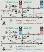
This is "charge transfer supply":
One can choose high power mosfet and diodes.
Honestly, I doubt I can face another amp project. I'm still looking for time to do: VSSA; SSA; re-do the Blame; finish LME49810-bipolar; and today I looked at briged amps
Not to mention my speaker projects...
This is "charge transfer supply":
One can choose high power mosfet and diodes.
Honestly, I doubt I can face another amp project. I'm still looking for time to do: VSSA; SSA; re-do the Blame; finish LME49810-bipolar; and today I looked at briged amps
Not to mention my speaker projects...
Attachments
I'm a little burnt out myself after building three tube amps in a row then selling them all. Replace the 0.47uf input cap with a 0.1uf. A better match for this amp.I remember I strictly adhered to your schematic. Yes, input cap is Wima 0.47uF.
This is "charge transfer supply":
One can choose high power mosfet and diodes.
Honestly, I doubt I can face another amp project. I'm still looking for time to do: VSSA; SSA; re-do the Blame; finish LME49810-bipolar; and today I looked at briged amps
Not to mention my speaker projects...
Replace the 0.47uf input cap with a 0.1uf. A better match for this amp.
OK. I'll try it. Thank you.
M.
It would seem that the MoFo is related to this ZCA amp.
Build This MoFo!
24v smps 5a LED lighting bricks work very well as Class A psu’s. If you need more volts use a DC to DC booster to get up to 50v.
Build This MoFo!
24v smps 5a LED lighting bricks work very well as Class A psu’s. If you need more volts use a DC to DC booster to get up to 50v.
The input impedance is partly set by the pot you use. 47K is a good place to start.
But better than a ZCA is a MCA.
Thank you for the reply but there is significant hum even after using a choke and 40000uF capacitance. What is your recommendation to get rid of that hum. Its not groundloop as it reduces with added capacitance. I tried using 0.1F as well but it didnt vanish completely.
- Status
- This old topic is closed. If you want to reopen this topic, contact a moderator using the "Report Post" button.
- Home
- Amplifiers
- Solid State
- ZCA 5 watt mosfet amp