Thanks a lot!
Both for the nice words, and also for the tip.
We don't have so many complaints, we had maybe 10 complaints all together about the ZAPfilter out of some 1500 units sold. So it's a small percentage. But of course we try to improve customer support at any time, and in fact on our danish website we have discussion boards for all our products groups, where customers can exchange comments and experiences.
Can be found here: http://www.lcaudio.dk/qna.htm
All the best
Dear P-A and other diyers, sorry for inconvenience, but I promised to post that here.
Dear Lars,
This is the acknowledgement of receipt back my pre paid funds of
  1178 for LC audio ZAP player to my account exactly after _THREE and a HALF YEARS_.
Thank you
p.s. will be in the evening definitely
Dear Lars,
This is the acknowledgement of receipt back
my pre paid funds of 1178 for LC audio ZAP player to my account exactly after _THREE and a HALF YEARS_.Thank you
p.s. will be
in the evening definitelyDear Deniz,
>however this one had +200mV dc on the right channel, the previous had +60mV on left channel,
that means that the dc shift doesn't caused by DAC dc output shift,
but for the complete check could you please connect _both_ Zapfilter2 inputs to _one_ (LOA(pin 11) or LOBN(pin 13), ROA(pin 18) or ROBN(pin 16)) SM5864 output. Now you can measure dc offset for different channels, while the input dc offset will be zero and common-mode voltage will be 2.5 V. Please e-mail me dc measurements, may be I can help you. Does the dc drift changes with time?
Hi all again,
Mr. Clausen i am not discussing your design with you, just trying to put out some ideas that may lead to solve the problem,
Yesterday i measured dc at Zapfilter inputs precisely, all were 2.523 except L+ which was 2.522, i measured -1.6mV between L+ and L-. If the dc error at Zapfilter left output were caused by an error at DAC output then it is supposed to be negative under these circumstances, but it is +60mV. Then i swapped polarities, connected negative DAC outputs to L+ of zapfilter and positive outputs to L-, nothing changed dc error was still there at +60mV. Connecting the Zapfilter left inputs to right DAC outputs did not change this situation either,
1.6 mV error in DAC output i think is quite normal and should be something Zapfilter can tolerate.
The trimmer resistor trick you suggested is then just a band aid solution and i refuse to apply that, as there are other such primitive solutions as series caps at outputs !!??
Thanks Dimitri, your suggestion is very smart, when both Zapfilter inputs are fed from the same DAC outputs everything will be clear, i will try that and soon report the results,
Deniz,
Sorry to revive this old thread, but any update on the problem Sarman or others? The problem is, I have exactly the same issue with DC offset as you  . I'm using the Zapfilter in my Sony SCD-XA3000ES player, it uses balanced voltage output DAC, BB's DSD1608. Old analog stage completely disconnected. Since the Zapfilter has gain of 2, I'd only installed a simple 1:1 10K voltage divider between the DAC and Zapfilter inputs as advised by LC Audio. The sound is great, so no problem here.
After powering up both channels stay below 2mV of DC offset, however in a couple of minutes the left channel climbs somewhere to 100mV (changing). Right channel fine (<2mV). When I open the player and let the fresh air get in (the zapfilter+its PSU get really hot in there, I cannot even touch the regulators) the DC offset on the left channel gets down. I even succeeded in getting below the 2mv level. So a problem with temperature instability it seems. Moreover I found that a connected load (amplifier's attenuator) helps the matter, without anything connected to Zapfilters outputs, the DC offset gets to some extreme levels (see included measurements). The DC offset of the DAC is negligible, below 1,6mV.
Zapfilter outputs:
LEFT CHANNEL: +toG -190mV -toG -300mV +to- 94mV
RIGHT CHANNEL: all around 1mV
Zapfilter inputs:
LEFT CHANNEL: +toG 1,292V -toG 1,294V +to- -1,6mV
RIGHT CHANNEL: +toG 1,297V -toG 1,298V +to- -0,7mV
I'm posting it here before contacting LC Audio, maybe someone would help. I tryed to send an e-mail to Sarman, but the forum doesn't allow me to (some message about reduced forum privileges pops up). Could somebody help me how to contact him?
. I'm using the Zapfilter in my Sony SCD-XA3000ES player, it uses balanced voltage output DAC, BB's DSD1608. Old analog stage completely disconnected. Since the Zapfilter has gain of 2, I'd only installed a simple 1:1 10K voltage divider between the DAC and Zapfilter inputs as advised by LC Audio. The sound is great, so no problem here.After powering up both channels stay below 2mV of DC offset, however in a couple of minutes the left channel climbs somewhere to 100mV (changing). Right channel fine (<2mV). When I open the player and let the fresh air get in (the zapfilter+its PSU get really hot in there, I cannot even touch the regulators) the DC offset on the left channel gets down. I even succeeded in getting below the 2mv level. So a problem with temperature instability it seems. Moreover I found that a connected load (amplifier's attenuator) helps the matter, without anything connected to Zapfilters outputs, the DC offset gets to some extreme levels (see included measurements). The DC offset of the DAC is negligible, below 1,6mV.
Zapfilter outputs:
LEFT CHANNEL: +toG -190mV -toG -300mV +to- 94mV
RIGHT CHANNEL: all around 1mV
Zapfilter inputs:
LEFT CHANNEL: +toG 1,292V -toG 1,294V +to- -1,6mV
RIGHT CHANNEL: +toG 1,297V -toG 1,298V +to- -0,7mV
I'm posting it here before contacting LC Audio, maybe someone would help. I tryed to send an e-mail to Sarman, but the forum doesn't allow me to (some message about reduced forum privileges pops up). Could somebody help me how to contact him?
Hi Karlosak,
This e-mail i received in 8th Aug. 2003 was the last communication we had with Lars, unexpectedly it solved the problem exactly. And guess what.. It was his mistake.. Read on..
Dear Mr. Salman
Did you solve this problem to your satisfaction?
We have found a new solution to this problem, that has turned out to be the result of our subcontractor using transistors with a different hfe sorting than we prescribed. This caused the input to be slightly common mode DC sensitive, even if DC should be completely undetectible to the first stage.
It can be solved simply by adjusting the common current mirror 10%, by mounting a 1k0 SMD resistor on top of the existing 100 Ohm resistor in the current mirror. (Not in the signal path).
After this the ZAPfilter input will be DC stable up to around 6V common mode, and the DC servos will be centered from 0 - 2.5 Volts.
See picture here: www.lcaudio.dk/zf2dcfix.jpg
We regret the inconvenience caused by this component change, and we hope you enjoy your ZAPfilter after this modification has been introduced, and the problem is gone.
Best regards
Lars Clausen
Yeah, some weeks later i gave it a try, and yesss.. That was the cure. I hope it also helps for your situation.
After all the arrogant conversation he had here with everyone, i expected him to post this notice on this thread, but it never happened..
Thank you very much Sarman for the reply. I would like to try your solution, but the picture link doesn't work.
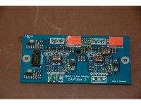
Could you please describe the position of the 100Ohm resistor in the current mirror? Or better, indicate the parts in the ZAPfilter picture:
Thank you!
Could you please describe the position of the 100Ohm resistor in the current mirror? Or better, indicate the parts in the ZAPfilter picture:
An externally hosted image should be here but it was not working when we last tested it.
Thank you!
Hi,
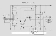
I don't remember the exact position of the resistor. I must open my cdp again to take a photo of the fixed ZF2 but this is quite a task. Instead i highlighted the resistor on the schematics of the ZF2. You can easily identify the resistor from the schematics,
I don't remember the exact position of the resistor. I must open my cdp again to take a photo of the fixed ZF2 but this is quite a task. Instead i highlighted the resistor on the schematics of the ZF2. You can easily identify the resistor from the schematics,
Attachments
didn't work
Sarman,
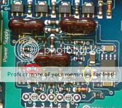
the trick you mentioned didn't work. I used 1K0 SMD resistors in parallel to the 100R original ones (see enclosed picture for their location) in both channels. Maybe it helped a little, the offset is now around -80mV (+toG) most of the time and takes a little longer after power up to kick in. The negative phase (-toG) is worse though, around -190mV, but still better than before. The right channel is free of any DC (<2mV).
Since there is max. 1,5mV offset between the balanced pairs at both ZAP inputs, its definitively a ZAPfilter issue, not the DAC. I'll contact LC Audio, if they don't suggest some fix, I'll demand a replacement.
I don't get why the right channel is perfectly fine but the left channel shifts badly. Maybe the design is sensitive to parts' tolerances and I've got a few bad ones. Hope the next unit will be fine. I'll post when LC Audio express their opinion.
Nevertheless, thank you Sarman for the effort.
Sarman,
the trick you mentioned didn't work.
I used 1K0 SMD resistors in parallel to the 100R original ones (see enclosed picture for their location) in both channels. Maybe it helped a little, the offset is now around -80mV (+toG) most of the time and takes a little longer after power up to kick in. The negative phase (-toG) is worse though, around -190mV, but still better than before. The right channel is free of any DC (<2mV).Since there is max. 1,5mV offset between the balanced pairs at both ZAP inputs, its definitively a ZAPfilter issue, not the DAC. I'll contact LC Audio, if they don't suggest some fix, I'll demand a replacement.
I don't get why the right channel is perfectly fine but the left channel shifts badly. Maybe the design is sensitive to parts' tolerances and I've got a few bad ones. Hope the next unit will be fine. I'll post when LC Audio express their opinion.
Nevertheless, thank you Sarman for the effort.
Hi Karlosak,
I thought maybe i am wrong about the resistor( there are other 100 ohm resistors on the schematic, and to my memory it was the one on the first stage).
So I opened inside my cdp and checked where the 100 ohm resistor is. I cannot take a photo in cdp because the zf2 is placed in a very tricky place, however i can see the modification through a hole in the main PCB of the cdp. I took a photo of my old Zapfilter (which is abused quite a lot!!), and highlighted the actual 100 ohm resistor. Sorry for the wrong information if this picture proves i highlighted the wrong resistor on the schmenatic on my previous post.
Attachments
Yes, you were wrong. 
The resistor you previously highlighted in the schematic is in a red circle, the resistor in a yellow circle is the right one, it's in the second stage of Zapfilter :
:
This time the effect was readily evident - but in a negative way: -0.8V left and -0.4V right. I didn't realize I would need bigger resistance in my case, since the offset was negative.
The resistance of this resistor is crucial though. Just a little change of 10Ohm made this shift. I left only 1K0 there, around +7V DC at the outputs! Then I put 160R in there (nothing better at hand), around +1.9V DC. Finally I put together a parallel combo of three resistors that measured 122R and that worked! It started at +200mV and quickly settled to zero (<2mV). I haven't tested it yet in an enclosed player for a longer time though.
I'll leave the right channel as is (no problem there), and aim at 115-118R in the left channel. I'm buying a bunch of 82R-150R SMD resistors tomorrow for a piece of mind I'll post then what worked (if anything).
The resistor you previously highlighted in the schematic is in a red circle, the resistor in a yellow circle is the right one, it's in the second stage of Zapfilter
:
This time the effect was readily evident - but in a negative way: -0.8V left and -0.4V right. I didn't realize I would need bigger resistance in my case, since the offset was negative.
The resistance of this resistor is crucial though. Just a little change of 10Ohm made this shift. I left only 1K0 there, around +7V DC at the outputs!
Then I put 160R in there (nothing better at hand), around +1.9V DC. Finally I put together a parallel combo of three resistors that measured 122R and that worked! It started at +200mV and quickly settled to zero (<2mV). I haven't tested it yet in an enclosed player for a longer time though.I'll leave the right channel as is (no problem there), and aim at 115-118R in the left channel. I'm buying a bunch of 82R-150R SMD resistors tomorrow for a piece of mind
I'll post then what worked (if anything).Hi Karlosak,
Your experiment does not sound like the right thing to do. Lars' explanation of the fix is that it increases the safety margin for sensitivity to common mode voltage in the inputs of the ZF. So there is no optimum value for the current mirror resistor, which you're trying to find.
This evening i did some measurements. My ZF installation has 2.523 V common mode voltage which is near perfectly identical on all the four inputs. My cdp uses two DAC chips, one for each channel averaging two DAC channels for each audio channel. So this is no surprise. The outputs read 0.0 mV dc on both channels. And these figures are rock stable... No change after heat-up or prolonged playback.
Bearing in mind that your ZF2 has half the dc as my ZF2 in the inputs it is more likely that your problem is something else. Maybe you have a faulty DC servo on the left channel. And let me remind you that none of my ZF2 channels behaved perfect before the modification. It is just that one was performing much worse than the other. You say your ZF2 right channel works fine. This suggests that at this point you'd rather request a replacement rather than experimenting.
Sarman said:Hi Karlosak,
Your experiment does not sound like the right thing to do. Lars' explanation of the fix is that it increases the safety margin for sensitivity to common mode voltage in the inputs of the ZF. So there is no optimum value for the current mirror resistor, which you're trying to find.
Dear Sarman,
I don't want to argue with you, I read Lars' post and grasped it the same way. However, his explanation is not correct IMHO. Mind you, I observed the same behavior in the working right channel. You increase that resistor value, the DC goes proportionally up and vice versa (obviously only true after the DC servo fails to correct).
What's more important - when I use 110R in the left channel, everything works perfectly, after 2 hours in the enclosed player all outputs are still below 1.5mV
And that's all what matters! It's interesting you're getting flat 0.0mV though, all of my outputs slightly fluctuates around 1mV now. I've received a reply to my e-mail to LC Audio, but they suggest just a RMA reguest on their site. Their technical support is not so skilled or interested in the problem probably. I'll try to make them forward my e-mail to the designer of the ZAPfilter (Lars Clausen?) and get his opinion about the matter. Stay tuned
I got cuirious about the servo design as it appears to be a "trade secret" and as such omitted from the published schematic. After staring at low-res pics for almost two hours i think i see the way it works. Would be nice if someone in possesion of a board (Lars? ) can confirm.
Sorry about the ugly drawing.
) can confirm.Sorry about the ugly drawing.
Attachments
Sound cuts in/out after a few minutes
I have different issue...
After the initial time delay for the relays, I get normal signal from the ZF2/ After a couple of minutes (between 1 and 2), the signal comes and goes. I get about ten seconds of signal, then one second of cur-out... Repeats indefinately?
Any ideas?
Thanks,
Dale
BTW, I get about +/-9.3V and one of the pass regs gets VERY hot...Voltage output is about 8.7V
- Status
- This old topic is closed. If you want to reopen this topic, contact a moderator using the "Report Post" button.
- Home
- Source & Line
- Digital Source
- Zapfilter DC offset trouble, help needed