I doubt there is a significant difference between any of the XX05 3-terminal regulators. I really like Per Anders super regulator boards, but if you must use a drop in replacement, these Dexa regulators look like a good value...
http://www.partsconnexion.com/catalog/semiconductors.html
http://www.partsconnexion.com/catalog/semiconductors.html
Are you trying for a drop in replacement for a pre-existing circuit or looking for a chip you can design around?
In my opinion Linear Technologies makes among the best regulators, with a few National Semi and Sanyo's that are also not so bad. I really like the LT1175 and LT1185 if you can design your own regulator board. Their suggested design is pretty good too, not a lot of tweaking needed. Biggest issue with the LT regulators is that most of them are only available in surface mount now a days. However I think you could make a small drop in surface mount to 3 pin as a replacement for a typical 3 pin regulator. Most feel that the adjustable regulators offer better regulation than the non-adjustable fixed regulators that are so common. Having said that, I think you fill find that the design of the circuit will have a greater impact than simple chip selection. Of course they need to be addressed together, a better chip with a better regulator chip will be better, but don't neglect the rest.
In my opinion Linear Technologies makes among the best regulators, with a few National Semi and Sanyo's that are also not so bad. I really like the LT1175 and LT1185 if you can design your own regulator board. Their suggested design is pretty good too, not a lot of tweaking needed. Biggest issue with the LT regulators is that most of them are only available in surface mount now a days. However I think you could make a small drop in surface mount to 3 pin as a replacement for a typical 3 pin regulator. Most feel that the adjustable regulators offer better regulation than the non-adjustable fixed regulators that are so common. Having said that, I think you fill find that the design of the circuit will have a greater impact than simple chip selection. Of course they need to be addressed together, a better chip with a better regulator chip will be better, but don't neglect the rest.
Your help please with IN/Out wiring for this Reg board
Thanks for the suggestions! This got me thinking about a discrete regulator. This one was suggested (schematic)
http://db.audioasylum.com/cgi/m.mpl...=regulator+john+swenson+green+led&r=&session=
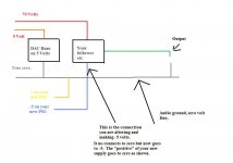
I have a dumb question in the interest of self-preservation. Preceding this -5V reg board will be a simple bridge rectifier and smoothing cap. Does the + rail of this unreg psu board connect to the V- input or the Ground of the -5V reg board?
Also, in looking at this schematic, I understand that VOUT- lead goes to the -5V input of the analog board it's powering, but what about the other lead (i.e. ground)? Do I also take the output from the GND on the schematic? Does that GND reflect the point at which the ground reference Input and Output land?
Thanks for the suggestions! This got me thinking about a discrete regulator. This one was suggested (schematic)
http://db.audioasylum.com/cgi/m.mpl...=regulator+john+swenson+green+led&r=&session=
I have a dumb question in the interest of self-preservation. Preceding this -5V reg board will be a simple bridge rectifier and smoothing cap. Does the + rail of this unreg psu board connect to the V- input or the Ground of the -5V reg board?
Also, in looking at this schematic, I understand that VOUT- lead goes to the -5V input of the analog board it's powering, but what about the other lead (i.e. ground)? Do I also take the output from the GND on the schematic? Does that GND reflect the point at which the ground reference Input and Output land?
Re: Your help please with IN/Out wiring for this Reg board
A separate PSU will be isolated due to the separate secondary winding.
Keep the regulator output flow and return separate until they reach the PCB. Tie the more positive lead to zero volt connection. Tie the more negative lead to the -5V connection.
it does not matter.riotubes said:Preceding this -5V reg board will be a simple bridge rectifier and smoothing cap. Does the + rail of this unreg psu board connect to the V- input or the Ground of the -5V reg board?
Also, in looking at this schematic, I understand that VOUT- lead goes to the -5V input of the analog board it's powering, but what about the other lead (i.e. ground)? Do I also take the output from the GND on the schematic? Does that GND reflect the point at which the ground reference Input and Output land?
A separate PSU will be isolated due to the separate secondary winding.
Keep the regulator output flow and return separate until they reach the PCB. Tie the more positive lead to zero volt connection. Tie the more negative lead to the -5V connection.
Thank you very much Andrew and Mooly! Yes, the whole circuit is new;it was spec'd for me. On the link below, I've drawn in the power rails for the three boards (unreg psu, -5v reg and I/V board) for the -5V. I hope I have interpreted Andrew's feedback correctly, but would appreciate someone double checking this for me. Here's the link to the diagram...Thanks!
http://gallery.audioasylum.com/cgi/...UserImages=31915&session=&invite=&w=960&h=720
http://gallery.audioasylum.com/cgi/...UserImages=31915&session=&invite=&w=960&h=720
Mooly said:Hi,
For 30 ma I think I would use a shunt regulator rather than series pass.
Why is that? I didn't believe shunt was inherently lower noise or anything.
Hi,
Lower impedance at HF right where you need it, on the pins of the I/C") It's only practicable at very low currents of course, but I have found it very good.
It's only practicable at very low currents of course, but I have found it very good.
richie00boy said:
Why is that? I didn't believe shunt was inherently lower noise or anything.
Lower impedance at HF right where you need it, on the pins of the I/C
It's only practicable at very low currents of course, but I have found it very good.you guys are so eager to help yet I'm not able to upload a pdf or png file (under 30kb)...not sure if its my machine or the website...
anyway, here is an attempt to post two more links into my photo gallery at asylum...if these don't work I'll try tonight from home....
Link directly to circuit:
http://gallery.audioasylum.com/cgi/...ession=&&moniker=RioTubes&invite=&w=960&h=720
General link into my photo gallery. the specific circuit is last one on bottom/right...scroll all the way down:
http://gallery.audioasylum.com/cgi/view.mpl?UserImages=31915
OK, three times a charm...
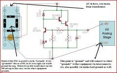
On the I/V board, a 70v reg powers the I/V board (not shown) and the designers says if a particular dac has zero volt output then it needs -5v instead of ground. So I show the -5v on the I/V board...but I'm not sure where to land the ground?...in addition to my general Q about whether ALL my PLUS and NEG power wires are correct through all three boards?
The I/V schematic is here...I'm not using the follower...
http://www.audioasylum.com/forums/pcaudio/messages/7005.html
Attachments
That looks OK. Just remember the aux PSU musn't have it's neg connected to "ground"
See if you follow it on the drawing. You want your little AUX psu connected as positive earth.
Just to confuse you even more it should be possible to derive a negative supply from your existing equipment, without having a separate tranny etc. How exactly depend on the PSU but involves only a few caps & diodes. Much neater -- no mains tranny etc.
Just in case I have missed it in all the posts, isn't there any OpAmps in the DAC that have a minus rail on them ( usually pin 4 )
Attachments
Thanks Mooly! Yes, as you indicate, I'm using a little 12V transformer to power the circuit above the PSU board. Also, no opamps in the I/V circuit.
OK, in looking at the I/V circuit on the link...if this were a voltage out DAC one would just need a 70V power supply and would connect the PLUS lead of the 70V reg to the 70V junction on the top of the I/V schematic and the GND of the 70V reg to the GND point on the bottom of the I/V schematic linked in my prior post #15. I Understand that. Just 2 leads. hot and cold.
But, because I use a Current Output Dac the circuit is designed to replace the GND with -5V input. So my VOUT- from -5V reg board goes to this GND point on bottom of IV. I got that. So what I am trying to understand is where the two other leads (the NEG from the 70V reg board) and the ground reference from the -5V board now land on the IV board? That's 4 leads (70 PLUS and NEG, and -5V and GND reference) instead of just the original hot and cold from the 70V if using a voltage out dac...still fuzzy on this last part
that's where the little 12V transformer
Hi,
Right is this what you mean, 1. Your 70 volts goes to the 70 volt rail. 2. Your point that says 0v - optional -5 now has to go to the -5 rail on your new supply. 3. The neg from the 70 volt rail still goes to "ground" or zero of the rest of the DAC circuit. 4. The positive of your new supply goes to this same ground in the DAC.
Will draw it.
 Is that what you mean. The DAC still runs on just 5 volts. Its just that point 0v optional -5 you are altering.
- Status
- This old topic is closed. If you want to reopen this topic, contact a moderator using the "Report Post" button.
- Home
- Design & Build
- Parts
- Your pick for best regulator needed for -5V 30mA