buzzforb:
You are apparently going to use Antek's AN-6224. Antek also offers 800VA and 1000VA toroids with 25V secondaries. Can you help me understand why the risks associated with the extra 1 volt are more compelling than the advantages of either of the significantly larger transformer alternatives?
Regards,
Scott
i belive it is more the 600VA option
")
For now I will stick to 18V toroid, 23V rails and 1,3A per channel.
Too many things can go wrong and I do not feel confident yet experimenting.
I m still considering the huge toroids though
sounds wise
just haul out if you need helpthats the reson we're here
I have been a bit silent cause of of too much crazyness going on at work...
Currently trying to decide what caps to get for the PSU.
I have the store's PSU boards and I am thinking of using all 12 cap positions by soldering 4 on the bottom side and 8 on the top side.
Something that is bothering me is selecting the voltage between 35V and 50V. The rails are going to be ~23V (18V socondaries) so either should be adequate.
The 35V dimensions will allow for 4x33KuF + 8x22KuF = 308KuF
The 50V dimensions will allow for 4x22KuF + 8x15KuF = 208KuF
I am seriously considering the 308KuF @35V option (it s about 15euros more expensive)
The drawbacks are that I am going to need double the space in the chassis and that mounting the board on it will be a bit trickier.
I will also probably need a soft start (which I already have anyway, again from the store).
Any suggestions or comments?
Last edited:
Both the 35v and 50v caps are more than enough rating for the project. Pass himself uses 25v caps in the factory F5.
Both of your capacitance ranges are more than enough, and will work quite well. Again, looking to the factory-build F5, it uses 120,000uf total, or 60,000uf per rail.
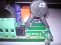
The CL-60 thermistors are the soft-start protection in the original circuit, but as you surmise, with 300,000uf of capacitance in the circuit, a 'more official' soft-start might be appropriate.
Both of your capacitance ranges are more than enough, and will work quite well. Again, looking to the factory-build F5, it uses 120,000uf total, or 60,000uf per rail.
The CL-60 thermistors are the soft-start protection in the original circuit, but as you surmise, with 300,000uf of capacitance in the circuit, a 'more official' soft-start might be appropriate.
The capacitance requires a slow charge circuit.
The transformer requires a soft start circuit.
The two circuits are different.
One can cobble together a combined circuit that does both jobs, but the slow charge part is severely compromised by being fitted on the primary side. Slow charge should be fitted on the secondary side.
The transformer requires a soft start circuit.
The two circuits are different.
One can cobble together a combined circuit that does both jobs, but the slow charge part is severely compromised by being fitted on the primary side. Slow charge should be fitted on the secondary side.
yeah
over-engineering is way to go
living in Athens , with European (220-240Vac) mains , means that 10-15R/10A NTC (placed in primary side , of course) will perfectly do the job
if more conservative , then "classic" soft start gadget circuit but with NTC's instead fixed resistors - will be perfect and really soft start solution .
usual ones , with fixed resistors , aren't universal solution ...... charging time must be tweaked to ensure non-sparking of shorting relay contacts ; using NTC's instead fixed ress. , especially with prolonged delay , will ensure long life and proper operation of shorting relay contacts
Last edited:
CL60 is perfect for a high power 110/120Vac primary.
Put one CL60 on each of these primaries and you have an excellent soft start.
This shows in some of Pass schematics. The two 110/120Vac primaries have a CL60 on each.
When you need to series connect the 110/120Vac primaries for 220/240Vac operation, you still need the two CL60. This time the CL60 are effectively in series.
Note that in both supply situations the CL60s are NEVER in parallel.
Yep. I was already on it.
Googled and mousered it fast.
http://www.ge-mcs.com/download/temperature/920_325a.pdf
CL-30 is rated at 2,5R at 25 degress celcius and 8A of constant current flow, while CL-60 is rated at 10R at 25 celcius and 5A current.
Googled and mousered it fast.
http://www.ge-mcs.com/download/temperature/920_325a.pdf
CL-30 is rated at 2,5R at 25 degress celcius and 8A of constant current flow, while CL-60 is rated at 10R at 25 celcius and 5A current.
you would need 8 off CL30 to give you a total of 20r to limit the start up surge current.
you need 2 off CL60 for the same 20r.
BTW,
I consider 20r of limiter resistance to be far too low for all transformers under 1kVA and 220/240Vac.
They cannot use a close rated fuse, eg. 750VA would require a T3.1A and with only 20r for soft start, this fuse is likely to blow too frequently.
Another example. I am using 140r @ 240Vac for a 80VA transformer and it starts on a T500mA.
Last edited:
The issue in that case is that since the F5 works at ~180W, the constant current expected to be run through the thermistor on the primary side is a bit less than 1A.
This means that the CL-60 thermistor will work on ~20% of its max current capacity (5A), meaning at full F5 operation, it will be around 1R .
And 4 in series give 4R
On the other hand, a CL-90 (120R @25 celcius and 2A max capacity) will give an even bigger initial current reduction and will eventually work at 50% giving ~3R resistance at full F5 operation.
Another issue that concerns me is that the recomended max capacitance rating for them is ~1500uF @240VAC. Aren t we pushing them way above their comfort limits? According to the datasheet, this is not their max safety threshold, but rather an indicator that their life might be shortened.
Maybe we should use 2-3 in parallel? (Which of course starts another round of discussion about what happens if one of them burns and/or shorts...)
- Status
- This old topic is closed. If you want to reopen this topic, contact a moderator using the "Report Post" button.
- Home
- Amplifiers
- Pass Labs
- Yet another F5 building log