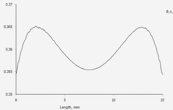
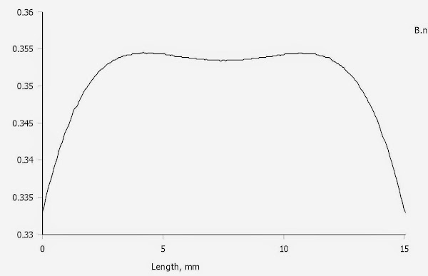
Based on your B.n-curve, the field is 0,3525 T +/- 11 %.
It is a little asymmetrical, but that could well be the FEMM simulation's fault.
So the 5 mm gap - 1 mm for the membrane yields a Xmax of 2 mm.
I don´t know how large your membrane is, but for a membrane equivalent to a 26" element, 4 mm Xmax is needed to get 100 dB @ 1 meter for 20 Hz.
2 mm gives 94 dB @ 1 m and 20 Hz. Perhaps that is enough, but if dipole compensation is needed the extra excursion will be needed.
Here´s a great tool.
@ solhaga & Bernt
Hi,
I've been playing with something similar in FEMM and would like to offer a couple of tips, if you don't mind.
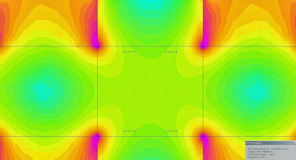
The sims you showed in posts 75 and 78 look OK, except that the graphs of flux density are very rough. The way to fix that is to reduce the mesh size in the area of interest. You don't want fine mesh for the whole model because the calculations will take forever. I would just add line segments around the outside of the magnet structure to close it off and create a separate area in the middle, then add a block label in there and set it to "air" with a mesh size of maybe 0.25mm or so. You might want to reduce the mesh size for the magnets as well.
Also, when you create the graph, you can choose the number of points. Increasing that above the default 150 can improve the resolution. That doesn't slow anything down so don't hesitate to try 1000 or 10000 and see what looks best.
Once you've got accurate graphs, you can start optimising the design. For example, one thing I was interested in was to get constant flux density across the width of the ribbon to minimise the bending force. I found that it's best if the distance from the diaphram to the magnets is about 1/4 of the width of the gap between the magnets, close to the geometry Bernt showed in post 78. If the diaphragm-to-magnet gap is too small, then flux density is higher at the edges of the ribbon than at the center. OTOH, if the gap is too large then the flux density is higher at the center than at the edges.
Of course if the ribbon is corrugated, that should should eliminate the bending problem, and you may not care about bending in that direction anyway. I would guess you're more interested in linearity, i.e. keeping the average flux across the ribbon constant as it moves back and forth. Unfortunately, I haven't played around to find a way to optimise that yet.
Regards - Godfrey
P.S. Remember to always plot either normal flux density or tangential flux density as appropriate, not total flux density.
Hi,
I've been playing with something similar in FEMM and would like to offer a couple of tips, if you don't mind.
The sims you showed in posts 75 and 78 look OK, except that the graphs of flux density are very rough. The way to fix that is to reduce the mesh size in the area of interest. You don't want fine mesh for the whole model because the calculations will take forever. I would just add line segments around the outside of the magnet structure to close it off and create a separate area in the middle, then add a block label in there and set it to "air" with a mesh size of maybe 0.25mm or so. You might want to reduce the mesh size for the magnets as well.
Yes, if you fix the mesh size, then they will look the same (or much closer).The field during travels of the membrane at three points,
the first one is the red one on the left in the simulation above:
...
middle:
...
to the right, should be the same as the first one though:
...
Also, when you create the graph, you can choose the number of points. Increasing that above the default 150 can improve the resolution. That doesn't slow anything down so don't hesitate to try 1000 or 10000 and see what looks best.
Once you've got accurate graphs, you can start optimising the design. For example, one thing I was interested in was to get constant flux density across the width of the ribbon to minimise the bending force. I found that it's best if the distance from the diaphram to the magnets is about 1/4 of the width of the gap between the magnets, close to the geometry Bernt showed in post 78. If the diaphragm-to-magnet gap is too small, then flux density is higher at the edges of the ribbon than at the center. OTOH, if the gap is too large then the flux density is higher at the center than at the edges.
Of course if the ribbon is corrugated, that should should eliminate the bending problem, and you may not care about bending in that direction anyway. I would guess you're more interested in linearity, i.e. keeping the average flux across the ribbon constant as it moves back and forth. Unfortunately, I haven't played around to find a way to optimise that yet.
Regards - Godfrey
P.S. Remember to always plot either normal flux density or tangential flux density as appropriate, not total flux density.
Last edited:

Once you've got accurate graphs, you can start optimising the design. For example, one thing I was interested in was to get constant flux density across the width of the ribbon to minimise the bending force. I found that it's best if the distance from the diaphram to the magnets is about 1/4 of the width of the gap between the magnets, close to the geometry Bernt showed in post 78.
When I worked with ribbons I had different width for the aluminium strips depending on how strong the field was, that is where in the gap the strip was; the stronger the field, the wider the strip.
If I´d go for aluminium strips as conductors on this bass planar, I´ll do the same even if the membrane will be so stiff that there is no risk of bending it.
This as I´ll probably get the best results if the forces are applied evenly onto the membrane.
Another side of that design principle is if I'd use copper wire, there is only small portion in each gap that can be used.
But I would only need a millimeter to get 4 turns of AWG30 side by side.
And two layers will only be 0,5 mm, plus the tape of course.
Other wire gauge and/or number of turns be used where the field is stronger.
It should be fairly easy to figure that out.
The great (and sole?) advantage of using copper wire is its easy deployment, one doesn't have to think of making some complicated pattern; just cross the wires when needed.
Using educational tools
These might come in handy in order to verify the simulations and testing the finished magnet system:
Iron filings:
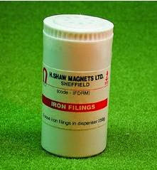
Small compasses:
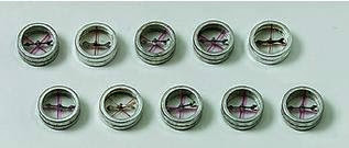
Iron filings inside a plastic compartment:
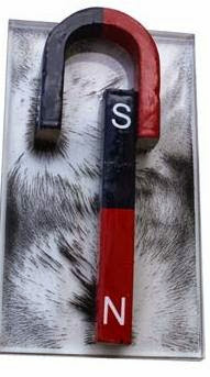
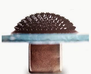
The ferro fluid, in order to get a 3D view of the field:
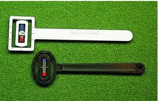
Field probe/Inclinometer, could be used as a quick test of the finished magnet system:
Also, a smartphone's compass could be used to some extent. Limited use though as it is hard to pinpoint where the sensor is.
Perhaps there are already apps for this")
These might come in handy in order to verify the simulations and testing the finished magnet system:
Iron filings:
Small compasses:
Iron filings inside a plastic compartment:
The ferro fluid, in order to get a 3D view of the field:
Field probe/Inclinometer, could be used as a quick test of the finished magnet system:
Also, a smartphone's compass could be used to some extent. Limited use though as it is hard to pinpoint where the sensor is.
Perhaps there are already apps for this
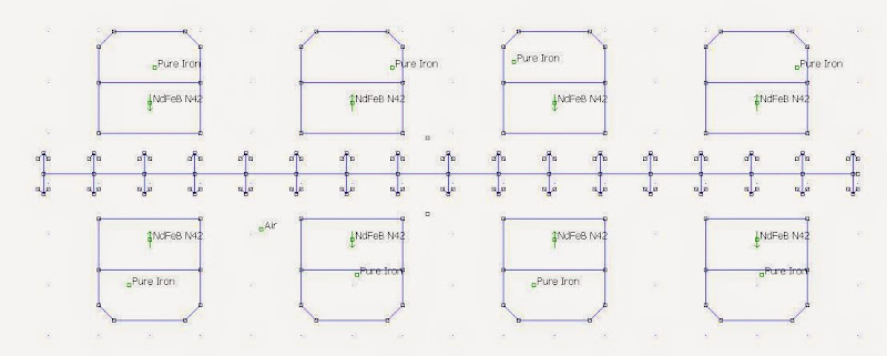
Zooming in
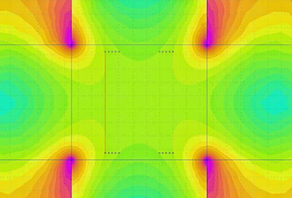
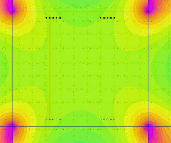
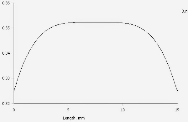
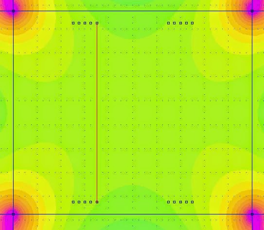
Following Godfrey's advice I did these simulations on the (perhaps) final design:

The copper wire will be within these limits, to the left:
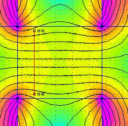

Field variation is 4 %.
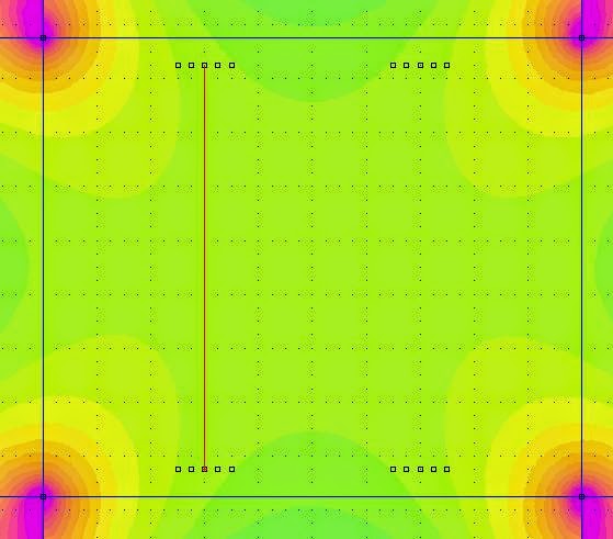
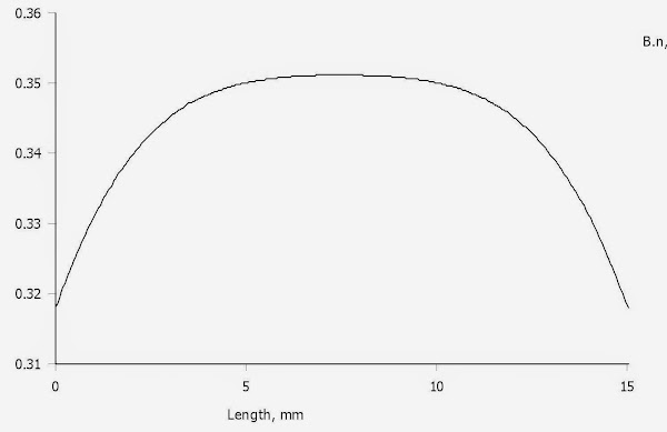
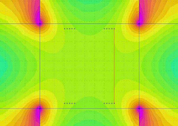
In the middle:
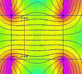

Field variation is 2,5 %.
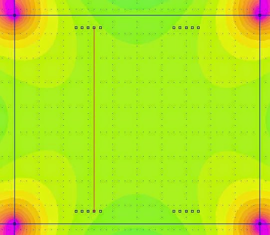
To the right:
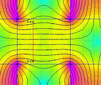

Field variation is 5 %.
Wire will of course also be on the opposite side of the gap.
So in this 2 mm spacing I can have 1 to 8 of AWG30 copper wire side by side.
To do the actual wiring will be very easy, just insert a needle pin were the wire shall change direction.
In the first tries the wire will only be taped to the foam.
I will later cut into the foam, wire and then seal. So the number of layers could be large as long as the foam board remains stiff enough after the seal.
How many turns/layers it will be is a later decision.
Following Godfrey's advice I did these simulations on the (perhaps) final design:
The copper wire will be within these limits, to the left:
Field variation is 4 %.
In the middle:
Field variation is 2,5 %.
To the right:
Field variation is 5 %.
Wire will of course also be on the opposite side of the gap.
So in this 2 mm spacing I can have 1 to 8 of AWG30 copper wire side by side.
To do the actual wiring will be very easy, just insert a needle pin were the wire shall change direction.
In the first tries the wire will only be taped to the foam.
I will later cut into the foam, wire and then seal. So the number of layers could be large as long as the foam board remains stiff enough after the seal.
How many turns/layers it will be is a later decision.
Sorry, one turn is of course 3 meters so it is roughly one ohm for every turn.Every turn of 1,5 meter means roughly half an ohm.
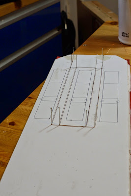
It's Voodoo time
Time to test the pin idea:
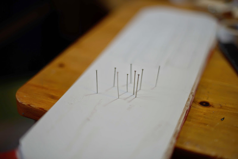
Placing the pins where the wire shall change direction:

Wound one turn:
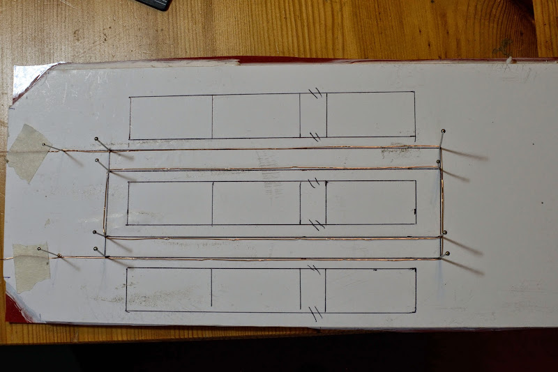
The wire is not fresh from the roll, so it is hard to get a straight line.
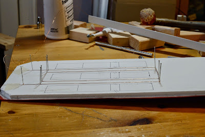
Some other angles:
Applying the first pieces of 74 film:
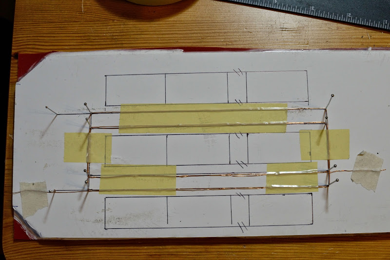
Turned out (sorry) that the piece of wire I tested only lasted one and a half turn, the coil is supposed to end and the top left pin.
Taped it all and removed the pins:

For the real deal I must be more careful to get the wire in the correct position.
I don't know if the 74 film is the most suitable tape to use. Maybe some resin or glue would be better.
Time to test the pin idea:
Placing the pins where the wire shall change direction:
Wound one turn:
The wire is not fresh from the roll, so it is hard to get a straight line.
Some other angles:
Applying the first pieces of 74 film:
Turned out (sorry) that the piece of wire I tested only lasted one and a half turn, the coil is supposed to end and the top left pin.
Taped it all and removed the pins:
For the real deal I must be more careful to get the wire in the correct position.
I don't know if the 74 film is the most suitable tape to use. Maybe some resin or glue would be better.
Full scale VC measurements
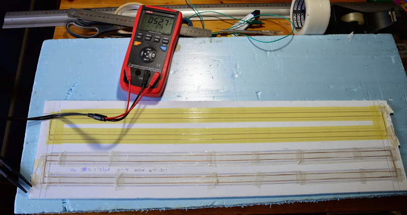
The lower VC is inserted in a cut-out of the foam, so that VC is ideally one mm high on its travel on the membrane between the magnet systems.
But the foam became flexible with the cut outs, so that method is ruled out.
This VC has four turns and a resistance of 3,99 ohm and an inductance of circa 50 uH.
The upper VC is a horizontal, one mm wide VC. Is is taped down with the 3M 74 film that bonded really well after a couple of hours.
Being horizontal the force from the VC on the foam will be better distributed and the Xmax is 0,75/2 mm more than for the vertical VC.
Although a vertical VC would be preferable as it should even out force field in-linearities.
This VC has three turns and a resistance of 2,99 ohm and an inductance of circa 33 uH.
So it's one ohm a turn, which is according to calculations.
But I don't know about the inductance, are the values within the expected range?
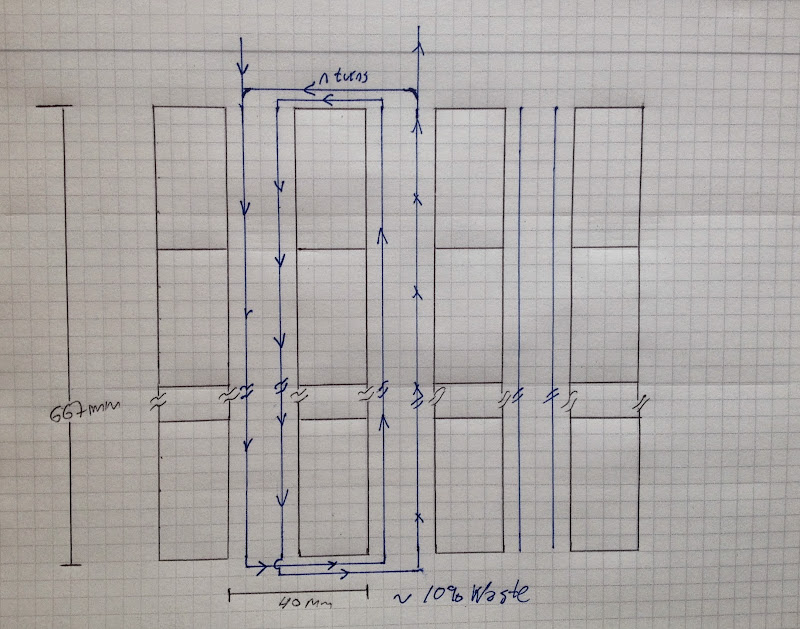
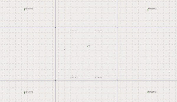
The VC is placed on the membrane which is illustrated below as the long horizontal line.
The view is from above, so upwards in the picture is forwards in reality.
The arrows visualizes the membrane's movement in the gap.
The lower VC is inserted in a cut-out of the foam, so that VC is ideally one mm high on its travel on the membrane between the magnet systems.
But the foam became flexible with the cut outs, so that method is ruled out.
This VC has four turns and a resistance of 3,99 ohm and an inductance of circa 50 uH.
The upper VC is a horizontal, one mm wide VC. Is is taped down with the 3M 74 film that bonded really well after a couple of hours.
Being horizontal the force from the VC on the foam will be better distributed and the Xmax is 0,75/2 mm more than for the vertical VC.
Although a vertical VC would be preferable as it should even out force field in-linearities.
This VC has three turns and a resistance of 2,99 ohm and an inductance of circa 33 uH.
So it's one ohm a turn, which is according to calculations.
But I don't know about the inductance, are the values within the expected range?
The VC is placed on the membrane which is illustrated below as the long horizontal line.
The view is from above, so upwards in the picture is forwards in reality.
The arrows visualizes the membrane's movement in the gap.


Ok, glad that we finally understand each other.My mistake.
I only looked at Post#91.
You placed them right.
Bernt
I can't use 3 mm aluminium foil, it is too wide to be within the linear region all through the VCs movement.To avoid cutting the foam ,
You could use adhesive 3mm alu and isolate the crossing "wires".
Then I lose 2,5 mm of Xmax.Maybe using both sides of the foam: front and back.
I was thinking you could use alu foil on both sides to get thinner membrane and avoid cutting in the foam .Might be possibly to avoid crossing alu foil using both sides.
Hope you understand my idea.It is difficult to explain in Words and even worse in a foring
languge.
Bernt
Hope you understand my idea.It is difficult to explain in Words and even worse in a foring
languge.
Bernt
Oops, that sounded a little harsh.I understood your suggestions perfectly but I have actually dismissed them earlier based on the reasons I stated in post #95.

I meant that I have considered such solutions earlier, your suggestions are of course brilliant as always so just keep 'em coming.
Improvements
Worked a little bit more with getting the field more linear:
Five possible places to have the wire (and five on the other side of course for the wire in the other direction):

So this looks extremely good, I think.
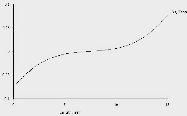
What about field in the other direction, which could result in movements of the membrane side to side?
Well, it isn't that small so it could be neglected:

But the good news is that it is the opposite on the other side:
Being connected via the stiff foam board, the forces are nullified.
Worked a little bit more with getting the field more linear:
Five possible places to have the wire (and five on the other side of course for the wire in the other direction):
So this looks extremely good, I think.
What about field in the other direction, which could result in movements of the membrane side to side?
Well, it isn't that small so it could be neglected:
But the good news is that it is the opposite on the other side:
Being connected via the stiff foam board, the forces are nullified.
- Status
- This old topic is closed. If you want to reopen this topic, contact a moderator using the "Report Post" button.
- Home
- Loudspeakers
- Planars & Exotics
- Yet another DIY Planar Bass