
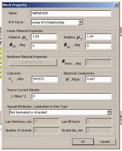
"my" magnet specificasions are American standard.
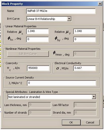
"your" magnet specifications are chinese standard.commonly used globally.
Grades of Neodymium
Bernt
"your" magnet specifications are chinese standard.commonly used globally.
Grades of Neodymium
Bernt


That is, it doesn't explain why the measuring points messes up your simulation nor the linear section of the curve in your previous post:
An externally hosted image should be here but it was not working when we last tested it.
I've really been trying to check what possible could differ in mine and båndsei's simulations.
I haven't been able to reproduce any of båndsei's results, but I have noticed that the results can differ a little on two seemingly equal circuits.
I guess it has something to do how the circuit is made and how the simulation starts.
Nevertheless, new simulations are made for my layout with a minimum of nodes and segments.
So in the simulations below, the iron is made of rectangular bars as before but the segments between individual bars has been removed.
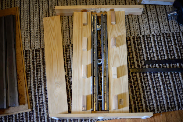
Design problem
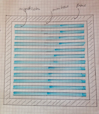
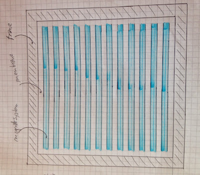
After much thought on how to mount the magnet structures and how the membrane will be suspended, I have come to the conclusion that the magnet structures will be vertically mounted instead of horizontally.
It will be 12 vertical "bars", still 50 mm cc but 67 cm high.
So the basic membrane will be quadratic and about 75x75 cm.
24 magnetic structures are then to be made.
I have three candidates for the magnet structure:
A: Grinding the outer shape, is takes the better part of an hour to do it.


B: Just mount the iron parts together, the "inner" bars are glued using epoxy. That takes perhaps 10 minutes per structure to do it but it can not be used immediately; the glue has to cure for 24 hours. This gluing has be done in A as well.
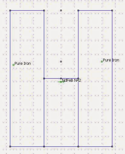
C: Exclude the "inner" bars.
There's very little to gain with A if any. It is simply not worth the 24 hours of heavy and filthy extra work of grinding the bars.
B has a stronger field than C but results in a 6 mm gap instead of the 10 mm C provides.
So mounting the membrane will be easier using C.
The VC is 1,5 mm though, so there should be plenty of space using B anyway.
C will perhaps require a 3-4 mm longer VCF in order to have the same Xmax.
On the other hand, C can provide a larger Xmax than B but it will be closer to Xmech at the bottom.
So: B or C?
After much thought on how to mount the magnet structures and how the membrane will be suspended, I have come to the conclusion that the magnet structures will be vertically mounted instead of horizontally.
It will be 12 vertical "bars", still 50 mm cc but 67 cm high.
So the basic membrane will be quadratic and about 75x75 cm.
24 magnetic structures are then to be made.
I have three candidates for the magnet structure:
A: Grinding the outer shape, is takes the better part of an hour to do it.
B: Just mount the iron parts together, the "inner" bars are glued using epoxy. That takes perhaps 10 minutes per structure to do it but it can not be used immediately; the glue has to cure for 24 hours. This gluing has be done in A as well.
C: Exclude the "inner" bars.
There's very little to gain with A if any. It is simply not worth the 24 hours of heavy and filthy extra work of grinding the bars.
B has a stronger field than C but results in a 6 mm gap instead of the 10 mm C provides.
So mounting the membrane will be easier using C.
The VC is 1,5 mm though, so there should be plenty of space using B anyway.
C will perhaps require a 3-4 mm longer VCF in order to have the same Xmax.
On the other hand, C can provide a larger Xmax than B but it will be closer to Xmech at the bottom.
So: B or C?
Last edited:
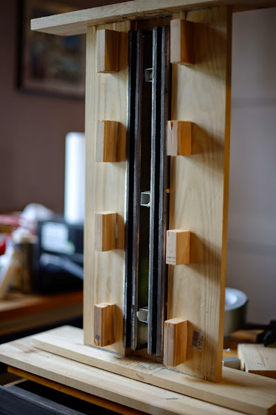
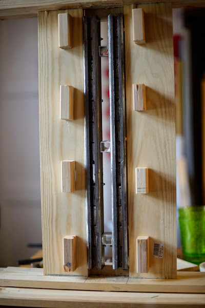
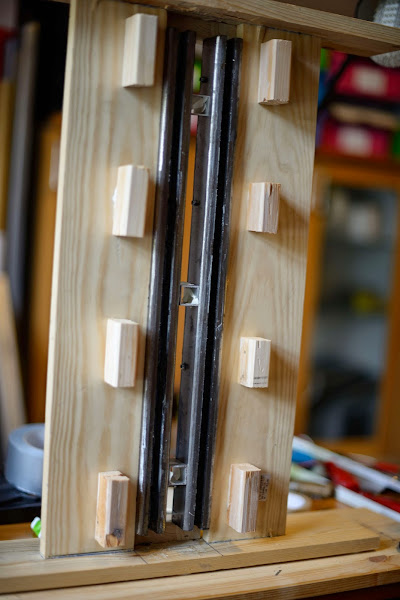
And the Winner is...
After have waited the 24 hours for the curing, it is with great disappointed I find that just gluing isn't enough; the magnetic forces are too strong and the inner metal bars pops out of place one by one.
I really glad though that I hadn't any of my fingers in between.
An option is of course to drill holes and use screws to hold the inner bars in place, but then the field will not be uniform across the 67 cm.
So I'd have to go for alternative C.
That will of course mean some re-design of VC, membrane and so on.
Unless one of you guys have a brilliant idea at this stage?
You could use thinner and cheaper magnets,and get same fieldstrength: app.0.42T.
Make a complete different magnet design. Like the Rubanoide.
ribbon speaker
I think this is something like Rubanoide magnetsystem and a mylarfilm diaphragm.
Bernt
Make a complete different magnet design. Like the Rubanoide.
ribbon speaker
I think this is something like Rubanoide magnetsystem and a mylarfilm diaphragm.
Bernt
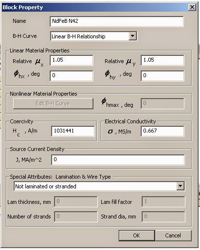
Using an 8 mm or 6 mm thick magnet would of course be cheaper, but it is not an option to change the magnets I have chosen as I'm stuck with the N42 40x20x10 mm I already have.
I can't see that I gain anything by changing the magnets either, as they will produce the same field strength anyway.
The Rubanoide magnet system was actually the instigator of this project and I have tested the idea on my old ribbon magnet system.
But I found that a direct magnet produced field is in my opinion not linear enough for the longer throw and the Vd that a bass membrane needs.
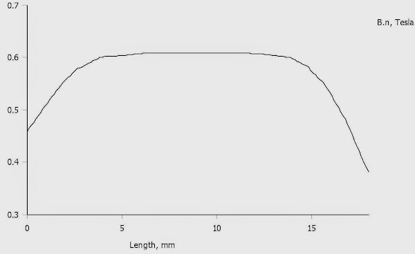
With alternative C I will get a 17 mm deep field within 2 %.
With only 8 turns in two layers, the VC will only be 1 mm high, so I will get an Xmax of 8 mm.
I can't see that I gain anything by changing the magnets either, as they will produce the same field strength anyway.
The Rubanoide magnet system was actually the instigator of this project and I have tested the idea on my old ribbon magnet system.
But I found that a direct magnet produced field is in my opinion not linear enough for the longer throw and the Vd that a bass membrane needs.
With alternative C I will get a 17 mm deep field within 2 %.
With only 8 turns in two layers, the VC will only be 1 mm high, so I will get an Xmax of 8 mm.


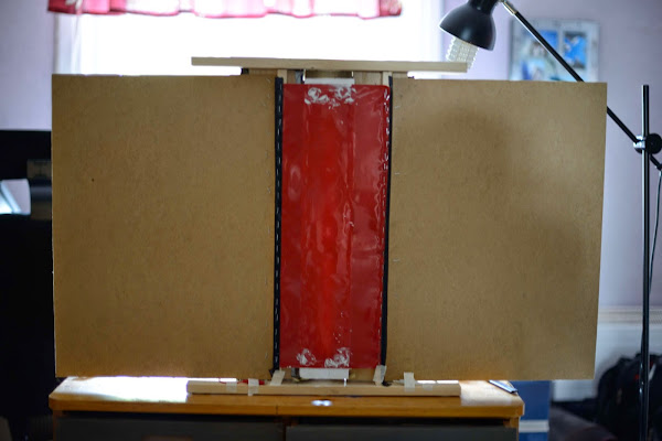
First measurement
First measurement of the second build:
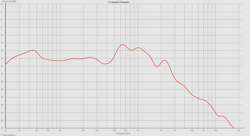
The dip at 400 Hz was due to the microphone placement.
This measurement was done at a distance of 10 cm.
The aim to have a frequency response towards 1 kHz seems fulfilled.
The membrane's suround was not tight enough and there are also other sources of resonances.
SPL is not much to brag about, but as this is only a tenth of the real membrane I'm not worrying.
I think this looks good enough to work on with.
First measurement of the second build:
The dip at 400 Hz was due to the microphone placement.
This measurement was done at a distance of 10 cm.
The aim to have a frequency response towards 1 kHz seems fulfilled.
The membrane's suround was not tight enough and there are also other sources of resonances.
SPL is not much to brag about, but as this is only a tenth of the real membrane I'm not worrying.
I think this looks good enough to work on with.
Change of plan(ar)s
This approach doesn't feel right, though.
It is way too complicated and I'll be blindfolded when attaching the VC for instance.
The resulting field isn't that great either; I could just as well make an ordinary planar.
My only concern now is how great Xmax I will obtain...
There will be some simulatins to be done
Something new, something old and something borrowed
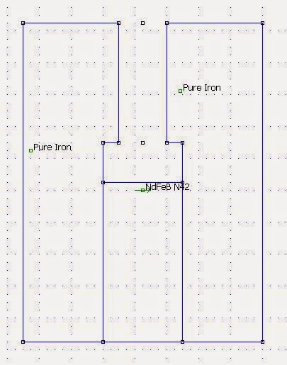
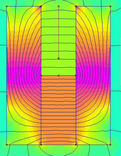
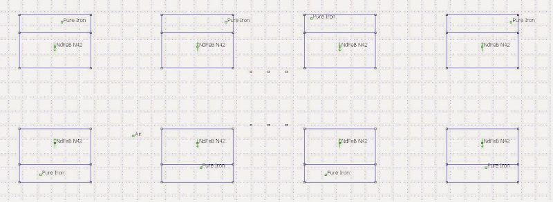
So I've been studying the planar threads thoroughly and done a lot of simulations and have come to the conclusion that only a push-pull design would satisfy my requirement of an linear Xmax well over 5 mm.
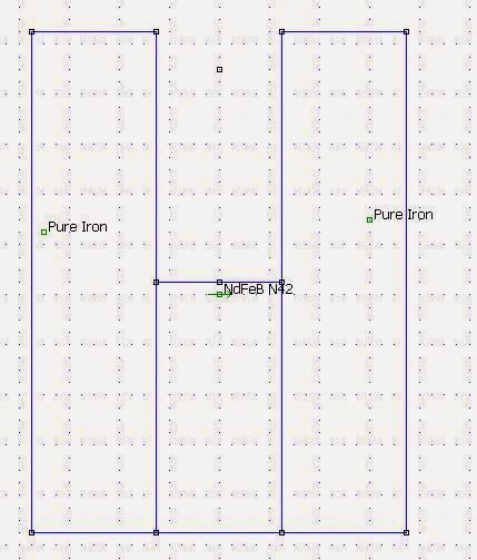
The basic design:
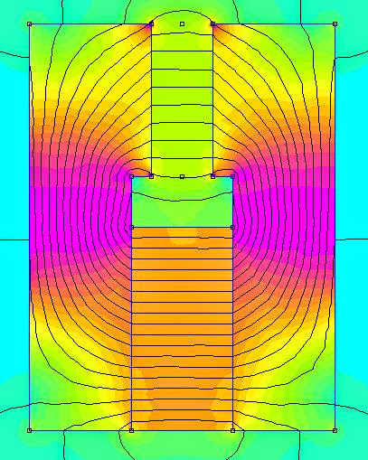
Simulation:
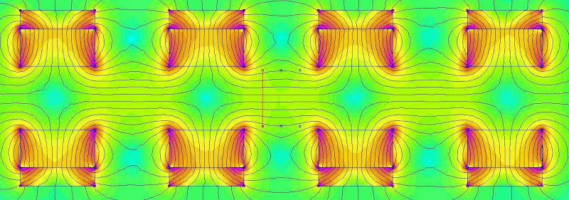
The field during travels of the membrane at three points,
the first one is the red one on the left in the simulation above:
middle:
to the right, should be the same as the first one though:
So I've been studying the planar threads thoroughly and done a lot of simulations and have come to the conclusion that only a push-pull design would satisfy my requirement of an linear Xmax well over 5 mm.
The basic design:
Simulation:
The field during travels of the membrane at three points,
the first one is the red one on the left in the simulation above:
middle:
to the right, should be the same as the first one though:
I have been told how to use simulation for planar.
I think this way is the right one .
 [/url][/IMG]
 [/url][/IMG]
 [/url][/IMG]
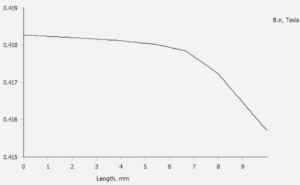
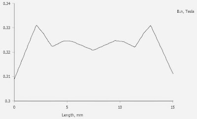
I am using B,t Tangential .To measure the field in the right "dimension"
 [/url][/IMG]
I have 5mm"gap".Your's 15mm.Using B,n for other direktion.
Bernt
I think this way is the right one .
I am using B,t Tangential .To measure the field in the right "dimension"
I have 5mm"gap".Your's 15mm.Using B,n for other direktion.
Bernt
Last edited:
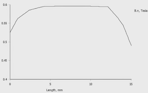
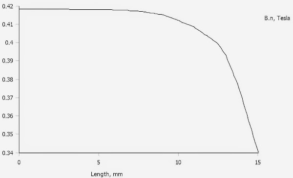
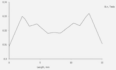
My curves showed the field for a point on the membrane that moves from -Xmax to +Xmax hence a field normal to the the red line.
My definition is a maximum of +/- 10 % deviation of the field, that travel divided by two is the linear Xmax.
The gap is 17 mm (Xmech is then 8,5 mm). Xmax is more or less the same, only the thickness of the membrane reduces it.
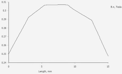
Your curve doesn't show much Xmax according to that definition:

Perhaps there are better places along the membrane to place the wire?
My definition is a maximum of +/- 10 % deviation of the field, that travel divided by two is the linear Xmax.
The gap is 17 mm (Xmech is then 8,5 mm). Xmax is more or less the same, only the thickness of the membrane reduces it.
Your curve doesn't show much Xmax according to that definition:
Perhaps there are better places along the membrane to place the wire?

- Status
- This old topic is closed. If you want to reopen this topic, contact a moderator using the "Report Post" button.
- Home
- Loudspeakers
- Planars & Exotics
- Yet another DIY Planar Bass