Also can anybody explain if i using led at cathode and CCS at plate, will I need bypass cap at cathode?
It will not be necissary or possible to bypass the LED. The impedence is so low that the cap size would be enormous. It is generally found however that a bypass of about 50uf does clean up noise and distortion to a worthwhile extent.
Using a plate load CCS and a cathode LED is a very good combination. Because the LED is a constant voltage element it should approximate to a constant current as well.
Shoog
Its a relief to know I got some numbers right ... just one more question and I will stop hijacking this thread.
Regarding droping the voltage (from 260v to 150v) for now, I was thinking of two options
1) Use a VR150/OD3 a single one for each channel with a series resistor and LM317 in the cathode to hold the bias at ~32-33mA will run the tube hot, haven't checked the plate dissapation yet, but should be ok i think.
2) one IXYSxxx (i have a couple of these at hand, didn't try them yet though) providing the b+ for each channel and regulate the current I want. Except all the drop will be on this device. I am sure there will be a need for a large heatsink.
I am thinking about trying (2) cos I don't have to drill anything, power transformer will run cooler and I can try a plate ccs later. But I am not sure whether putting a ccs in series with a plate choke is a good idea. If this is a bad idea is (1) ok ? From the contents of this thread I have a feeling (1) will sound the best, but would rather try it later as I don't want to do any drilling (in an apartment) now. Also leaves another thing to play with later")
Praveen
Regarding droping the voltage (from 260v to 150v) for now, I was thinking of two options
1) Use a VR150/OD3 a single one for each channel with a series resistor and LM317 in the cathode to hold the bias at ~32-33mA will run the tube hot, haven't checked the plate dissapation yet, but should be ok i think.
2) one IXYSxxx (i have a couple of these at hand, didn't try them yet though) providing the b+ for each channel and regulate the current I want. Except all the drop will be on this device. I am sure there will be a need for a large heatsink.
I am thinking about trying (2) cos I don't have to drill anything, power transformer will run cooler and I can try a plate ccs later. But I am not sure whether putting a ccs in series with a plate choke is a good idea. If this is a bad idea is (1) ok ? From the contents of this thread I have a feeling (1) will sound the best, but would rather try it later as I don't want to do any drilling (in an apartment) now. Also leaves another thing to play with later
Praveen
Hmmmmm,
Assuming you will be pulling approx 30mA(12B4 tube) + 20mA (shunt tube) per side and dropping 110V (260 - 150), the IXYS chip will be dissipating 11W, which is right on the device limit (don't believe everything you read on a datasheet, especially wrt to power dissipation capacity).
This link will help clarify how to calculate real world dissipation capacity
http://db.audioasylum.com/cgi/m.mpl?forum=magnequest&n=227&highlight=dn2540+sink&r=&session=
The 10 M45S displays 3.1 C/W Rjc, 4.1 C/W Rjs with insulator.
With a 30C ambient, 30C sink rise and a 100C junction
Pmax = 40/4.1 = just under 10W
pm
Thanks for catching that mach1, didn't realize there was more to it than VI < 40W  . Will use a power resistor to drop the voltage.
I wasn't planning to run a shunt tube if I was using the IXYS. In this case the plate choke runs directly after the ccs. Just wanted to know if it was ok to have a ccs in series with a plate choke cos I might just end up getting a nasty combination of ccs and choke together as a plate load or maybe they help each other and the combined effect might be better ... does anyone have any experience with this ?
If no one has any comments I'll just try using a resistor for dropping the voltage and compare with ccs before deciding what 'flavor of the day' I want.
Praveen
. Will use a power resistor to drop the voltage. I wasn't planning to run a shunt tube if I was using the IXYS. In this case the plate choke runs directly after the ccs. Just wanted to know if it was ok to have a ccs in series with a plate choke cos I might just end up getting a nasty combination of ccs and choke together as a plate load or maybe they help each other and the combined effect might be better ... does anyone have any experience with this ?
If no one has any comments I'll just try using a resistor for dropping the voltage and compare with ccs before deciding what 'flavor of the day' I want
.Praveen
Zen Mod said:
what you need is one nice plate choke ,and-tnx to low Ri of 12B4,that choke must not be enormous....in that case Ub will be around 150V,and just one OD will do the beeeezzzznissssss...
Hi Choky / Zen Mod and others reading...
I want to try plate choke on the 12B4! I have a pair of 100H, 50mA chokes, can it be used here with a 150V B+?
thanks!
pengboon said:
Hi Choky / Zen Mod and others reading...
I want to try plate choke on the 12B4! I have a pair of 100H, 50mA chokes, can it be used here with a 150V B+?
thanks!
just go for it
and REPORT results here
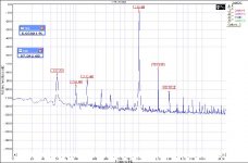
I just "retro-fitted" my preamp with plate chokes on the 12B4! It's playing now. I had to drop quite a lot of voltage (using RCRCRC) to reach 150V from 300V previously with resistor load (lots of heat!), and now using 1 0D3 each channel.
The sound seems more dynamic and clearer! IMHO, more "live" and "powerful" than before! Next, I'm going to do plate chokes on my DAC output...
Brian,
the DCR is slightly less than 1.4k
thanks everyone!
The sound seems more dynamic and clearer! IMHO, more "live" and "powerful" than before!
Next, I'm going to do plate chokes on my DAC output...Brian,
the DCR is slightly less than 1.4k
thanks everyone!
pengboon said:I just "retro-fitted" my preamp with plate chokes on the 12B4! It's playing now. I had to drop quite a lot of voltage (using RCRCRC) to reach 150V from 300V previously with resistor load (lots of heat!), and now using 1 0D3 each channel.
The sound seems more dynamic and clearer! IMHO, more "live" and "powerful" than before!
Brian,
the DCR is slightly less than 1.4k
thanks everyone!
I told ya

Clarification
So I've read through this whole thread and I'm pretty sure I've got a grasp on almost everything but I still have some questions. First let me start by saying I do have experience with tube equipment as I did a rebuild of my ST70, but that was following instructions so it was straight forward. I'm also capable of wiring a circuit as simple as this one. I'm doing an electrical engineering technology degree and am just starting courses in analog and power supply design so some of this discussion is a little over my head.
That said my question is about the whole filament, grid, plate, cathode business. I downloaded the data sheet and understand most of it. Are the following statements correct?
1) Grid voltage is the controlling (audio signal) voltage from input: Pin 2
2) Plate voltage is my B+ supply voltage: Pin 9
3) Cathode is my ground which has the regulator connected to it: Pin 1
I'm confused on the whole series/parallel filament part. The data sheet says pin 3 is the heater center tap and 4 & 5 are heater. Is parallel hookup simply taking my 6.3V taps from my transformer and wiring them to 3&4 or 3&5, then jumper two wires over to the exact same location on the other tube? How does series connection come into play and do these heater voltages require any sort of filtering or regulation?
Next, I plan to purchase a ready made PS like the one that is offered by Welborne Labs. To wind up with a regulated 320V would a transformer with output of 375-400VAC be appropriate? Are there any current considerations?
What voltage rating must the bypass caps be and any recommendations on good quality electrolytics and the smaller boutique cap?
And what is the story behind this whole plate choke business? What does it accomplish through voltage drop and inductance that simply lowering the plate voltage doesn't?
Final question, how do I build this pre so that it can drive a variety of amp input Z. My ST70 is on the order of 100k so I will first build for that. But what if I buy a solid state amp in the range of 20K-30K, what needs to be changed if anything at all?
I appreciate any help you guys can give me. I was seriously considering buying a Grounded Grid kit, but luckily I've come across this instead. I want to make an absolutely stellar line stage and don't mind spending the money to get it.
Zen Mod said:
I told ya
heh... should I rebuild my PSU to be choke loaded so I don't need to drop so much voltage?
pengboon said:
heh... should I rebuild my PSU to be choke loaded so I don't need to drop so much voltage?


1) Grid voltage is the controlling (audio signal) voltage from input: Pin 2
As to your `1,2,3 questions I believe you are right.
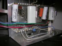
The toobe filaments draw alot more current at 6.3 volts. I run both mine from a single 12 volt adjustable regulator I.C. and its not referenced to B+. It can bee seen in the picture below. For me this has worked out just fine and the line stage is dead quiet even with your ear right at the tweeter! So personally I reccomend using 12.6 volts DC on the heaters. I did run mine from 6.3 volts but had regulator I.C. failures as a result. Warm up time at 6.3 volts was also ALOT longer.
Welbourne should be able to supply you with the correct transformer for their power supply running at 320 volts. Personally I've kinda been down a similar path already with a dofferent solid state regulator board from Germany... using 2 0D3 gas regulators in series per channel sounds ALOT better than the solid state board did and is less expensive. My main B+ supply is an Eico variable DC bench supply and it's main supply is choke filtered before it's regulator toobes.
I am using 2- 220 mf standard 63 volt rating Sprague electrolytics in parallel for the bypass electrolytics but also paralleled with a .1 Wondercap SETI. My output coupling caps are Multi-Cap PPMFX 5 mfd bypassed with a single .01 Infinicap. Note that my line stage is built on some Tektronix ceramic/silver terminal strips salvaged out of an old scope.
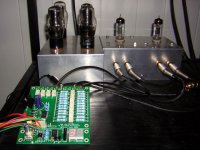
My most recent addition to the 12B4 line stage thanks to Luckylyndy is the Jos Van Eijndhoven remote attenuator. Jos is an engineer at Phillips but likes to design audio related stuff in his spare time. This attenuator is the best thought out design I've ever seen..... the attenuator allows just three resistors in the signal path per channel to adjust level. Only 6 relays and 12 resistors per channel are needed to give a 64 step continous step in level over a 70db range at 1 DB per step. A 2 digit LED resdout indicates the step of the level you are at as well as which input is selected. This is another huge improvement in sound quality and blows away my modified Daven series step attenuator switch. Jos's board also includes 4 input select relays. This is all controled through a standard generis remote that will put out Phillips RC-5 or EC-6 signals. There is also a combination encoder/push switch that also allows one to control volums and input select from the front panel. Changing to this attenuator was like rolling up a window shade in front of my speakers and the full remote control of level, input select, and mute is also VERY nice!
Jos's web site is here
Attachments
Zen Mod said:
should have thought of that huh... anyway just did it, and removed 2 RC stages, also reduced the R on the remaining stages. Getting a hum on the right channel now (think it's 100Hz), ARGGHH... hopefully will be able to solve it next weekend.
Don't know if any of you have ever seen this, but it's certainly the route I'd like to go if building a 12B4 preamp from the ground up. I emailed Emotive but perhaps you guys may know too; what are the two tubes in front of the 4 OD3 regualtor tubes. I did some reading on the 274B and it's certainly a sweet rectifier tube.
Emotive Audio Epifania
Mark, could you please clarify for me how I can obtain 12.6VDC for the heaters from a transformer. Will I need to purchase one separate from my power transformer or can it be obtained from the more standard 6.3VAC windings that accompany transformers designed for tube circuits.
I prefer to use a seperate transformer for just about everything when I build something. This way you are not stuck with an expensive boat anchor if you decide to change out something at some point. So yes, A seperate transformer for the filament and B+ is a good idea in my book unless you're cramped for space. To get the 12.6 volts DC just build up an inexpensive adjustable 3 amp regulator circuit. Total cost less transformer is about 5 bucks. Be sure to put the I.C. on plenty of heatsinking so it does not overheat and shut down. I mounted mine to the chassis.
Mark
Mark
jasonb84 said:Don't know if any of you have ever seen this, but it's certainly the route I'd like to go if building a 12B4 preamp from the ground up. I emailed Emotive but perhaps you guys may know too; what are the two tubes in front of the 4 OD3 regualtor tubes. I did some reading on the 274B and it's certainly a sweet rectifier tube.
Emotive Audio Epifania
$17,000! I hope it comes with K-Y!!!
- Status
- This old topic is closed. If you want to reopen this topic, contact a moderator using the "Report Post" button.
- Home
- Amplifiers
- Tubes / Valves
- Yet another 12B4 line stage, or is the 12B4 better than the Grounded Grid.....