Thanks Hi-Q,
I did read through all the posts, interesting. Only had mine a month, not got round to setting up the bias yet, must get round to doing that !
Reason I asked about the input caps is that I have an excellent pair here - ClarityCap MR 2.2uf, they are pretty big so might not fit under the bonnet anyway...
Thanks
There are no input capacitors, the amp is direct coupled except for the final stages that use a total of four 100nF coupling capacitors. I did try increasing my amps caps to 470nF with good quality audio types but the difference in sound, if any, was not really detectable to my ears. Fitting alternative manufacturer's valves made the biggest difference, that's not to knock the original Chinese valves fitted. They have been put into a rock groups guitar amplifier and gigged really hard without complaining, the sound they give in that application is loved by the guitarist. I guess the problem is that with Hi-Fi speakers and sources applied, one hears the sound in a different context and is able to hear the subtle changes made by valve substitution. I was a firm dis-believer in this until I tried it, I am still amazed how different valves can make such differences.

I have been watching with great interest the Yaqin 5881 thread:-
Yaqin MC-5881A amplifier improvements - diyAudio
The circuitry in places is virtually identical and the improvements/mods detailed are very tempting to try. For example, take doing away with the 30k long tailed pair resistor. Would a simple circuit as attached be capable of replacing the resistor with any advantage?
Also it is stated that if this is done the two plate resistors, currently 47k and 51k should both be made 47k?
In fact it had already been suggested to me that one of these resistors, possibly the 51k, should be made variable e.g. 39k with a series 22k preset. This would allow the outputs feeding the EL34's to be equalised.
Noted also is the change of B+ resistor from 5k1 to 12k, that seems a bit of a large jump to me and though it might lower the gain of the pre-amp, would it improve the sound quality?
Finally the feedback components (5k1 with 100pF cap), the cap is indeed a ceramic one in the MC10L, would a mica make any difference here? Would lowering the gain of the amp by changing these components to 1k2 + 500pF be an advantage?
I must say I am tempted to disconnect the OPT wires from the screens of the EL34's and connecting the suggested 47 Ohm resistor between plate and screen to give a triode configuration, just to find out how it sounds.
I realise that I have written more questions than answers, I have so many other projects going at the moment that it may be some time before I try any of these changes for myself, I was just wondering if someone else had seen these mods and tried them already. I hope to attach the pdf of the 2SC3468, interestingly it is available with a high gain suffix F which might be better. The 166 Ohm resistor is just a rough estimate, I would trim this to give the required current which, going by the voltages currently measured, I would reckon on being around 4mA.
I have put some of my circuit redraws on
Index of /lez/YAQIN MC10
I will shortly add some more photos showing voltages around the circuit.
Regards
Les
PS For some strange reason I cannot upload the jpeg and pdf even though they are very small in size. I will put them on my homepage too.")
Thanks Les, have just printed off your 'real' MC-10L manual !
Hello
I have just received my MC10L and it certainly is very 'bling' to look at.
So far no fuses have blown....
I spent the first couple of days wondering why it sounded so bad when compared to my Naim 180 clone integrated amp.
I know I should have checked the bias levels immediately but I just wanted to try it out !
They were all miles out, three were well over 400mV and one was less 320mV.
Once set to 350mV the difference was really obvious - no more did it sound like they were singing through a vat of lard, it sounded as sweet as many have reported before.
Lesson learnt - and apart from the size and shape of it I am pretty pleased.
Graham
ps. Les - thanks for writing that info doc - very interesting......
Hi, I have just got round to measuring my bias and all four read 400mv, must be a matched set then.
Should I still turn them down to 350mv ?
Also, I don't have anything long and thin enough to reach down into the pot without getting my fingers burnt. Is there a special tool for this purpose ?
Oh and talking of bling, mine is sited next to a gold painted wall !
Should I still turn them down to 350mv ?
Also, I don't have anything long and thin enough to reach down into the pot without getting my fingers burnt. Is there a special tool for this purpose ?
Oh and talking of bling, mine is sited next to a gold painted wall !
Hi, I have just got round to measuring my bias and all four read 400mv, must be a matched set then.
Should I still turn them down to 350mv ?
Also, I don't have anything long and thin enough to reach down into the pot without getting my fingers burnt. Is there a special tool for this purpose ?
Oh and talking of bling, mine is sited next to a gold painted wall !
My understanding is that 400mV is the upper limit - according to what is written on the top of the unit. You don't need a matched set as these trimpots mean you can set the bias for each valve independently.
My amp came with a long insulated allen driver - if you still have the box check in the bottom - where the mains lead was.
Graham
Ah got it thanks, missed that completely, right underneath and buried in the foam, they could have put it on the top.....
Ok, just had a go and what a frustrating little exercise that turned out to be, V1 being by far the worse to tune as the meter was going ballistic from 200 to 2000, so I let it settle down then turn the driver a fraction and swoosh it would swing miles away arrggg.... Eventually got it to 348, gently pulled out the driver and that would be enough to send it back up to 500 or so.....
How often do we have to do this ?
It is a bit fiddly, especially when it comes to removing the adjustment tool.
I had a similar problem with the wild voltage swing (not as much as 2000mV though) - this may have been caused by an intermittent contact of the DVM probes. Why aren't they 4mm banana sockets?, that would make life a lot easier.
As to how often, as often as it needs ! I don't know as I have had mine less than a week, perhaps somebody else may have an idea?
Did it sound any different after the adjustment ?
Hello all,
First of all, thank you all for posting. I have found this forum post extremely interesting and helpful. I am the new owner of a Yaqin MC-10 and am completely new to the valve amp scene but hoping you guys can help me. My speakers produce a lovely sound however there is always a low humming noise. While researching solutions to this problem I stumbled upon this site and decided to test the bias voltage (Mine is an MC10 MK2 with the external test points). On the top left and right valve (1 & 2) the voltage is approximately 0.392, whereas the voltage through the bottom left (3) read 18.7 and through the bottom right (4) read 23.4. I have tested this several times (after waiting a while, switching the unit on and off, switching plug sockets etc) and it always gives me these crazy results. Can anybody think of a reason why sockets 3 & 4 would give such a high result? Is there any chance that the bias needs adjusting and if so would those values be in the range the valves could handle?
Any help would be most appreciated as I'm currently too concerned to run the unit for anything other than testing.
Regards,
Gareth Davies.
Hello all,
First of all, thank you all for posting. I have found this forum post extremely interesting and helpful. I am the new owner of a Yaqin MC-10 and am completely new to the valve amp scene but hoping you guys can help me. My speakers produce a lovely sound however there is always a low humming noise. While researching solutions to this problem I stumbled upon this site and decided to test the bias voltage (Mine is an MC10 MK2 with the external test points). On the top left and right valve (1 & 2) the voltage is approximately 0.392, whereas the voltage through the bottom left (3) read 18.7 and through the bottom right (4) read 23.4. I have tested this several times (after waiting a while, switching the unit on and off, switching plug sockets etc) and it always gives me these crazy results. Can anybody think of a reason why sockets 3 & 4 would give such a high result? Is there any chance that the bias needs adjusting and if so would those values be in the range the valves could handle?
Any help would be most appreciated as I'm currently too concerned to run the unit for anything other than testing.
Regards,
Gareth Davies.
I am also a new owner and mine has the same fault. It blew one of the tubes... I am getting it looked at next week. It is a fault. You will need to get it checked. If I learn anything I will let you know...
Andrew
The voltages you state are crazy as 18.7V would either mean the valve is passing 1.87 Amps (Very Highly unlikely as the amp would be in melt down!) or the 10 Ohm monitor resistor has gone way high in value!
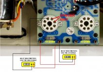
I wonder if your meter has auto ranged down and you are reading millivolts (mV) rather than Volts? There is a possibility that you may have a rogue valve that is affecting the bias supply but as one of the valves is sitting nicely at around 0.35V then this would suggest this is not the case. I do not have that many photos of the newer chassis layout but I have attached a picture of the left hand side. With the amp turned OFF, measure each of the 10 Ohm resistors with your multimeter, you can do this using the bias measurement points to save you removing the top cover. If the resistors seem OK, try setting up the bias on each of the left hand valves to around 0.35V using the trim controls.
If this cannot be achieved, pull the valve that is not responding and verify that the bias voltage of around -35V can be seen to be present as shown in the picture. Remember that it is a negative voltage so you have to put the Multimeter Black wire onto the valve pin*. If this is correct then the valve should be suspected, try another valve in this position. You should get proper biasing now unless you have more than one valve faulty which would be very unlucky. The reason for hum may be due to excessive current being drawn from the B+ line by the valves not being biased correctly. The excessive drain makes the supply smoothers work too hard to the point where the supply ripple increases. This will be at 100/120Hz rather than your mains supply frequency of 50/60Hz.
Hope you get the amp sorted
Les, Watford, England
*Not necessary with an electronic Multimeter but is suggested in case an Analogue type meter is being used.
Attachments
Last edited:
Thank you Les. I was advised by a repairer to urgently take it to him to avoid blowing all valves. But from your description I think I just have 1 rogue valve. I have the hum, 1 very hot valve and high bias in the affected side... BTW which way do I turn the adjusters to decrease the bias. I want to set it low for all valves as I add the new valve to avoid blowing any...
If you monitor the bias voltage at the valve holder as shown in my post #93, then adjust the relevant bias control for maximum negative voltage.
This will set the valve for minimum current. From my poor memory I think turning the controls fully anti-clockwise achieves this condition but I would advise checking with a meter as my 65 year old memory cannot be relied on where safety is concerned.
I have noted in other posts that a bias of 0.24V is recommended but I think this figure is a little 'cold'. From all of my research into comparable amplifier circuits, then 0.35V would appear to be a better figure to aim for and my amplifier has run quite happily at this setting for 3 years now.
Regards, Les
This will set the valve for minimum current. From my poor memory I think turning the controls fully anti-clockwise achieves this condition but I would advise checking with a meter as my 65 year old memory cannot be relied on where safety is concerned
.I have noted in other posts that a bias of 0.24V is recommended but I think this figure is a little 'cold'. From all of my research into comparable amplifier circuits, then 0.35V would appear to be a better figure to aim for and my amplifier has run quite happily at this setting for 3 years now.
Regards, Les
Hi Les,
I'm not an electronics expert by any stretch of the imagination however I'm quite confident the voltages I'm reading are correct because I manually have to adjust the multimeter sensitivity. To read the top left and right bias (which give the correct reading) I set the multimeter to 2000m whereas this just gives a reading of 1 for the two lower biases. If I set the sensitivity to 20 volts I still get a reading of 1 and therefore I have to set the meter to 200 volts which is gives me a reading of 23.4.
I have tried turning the amp off and testing the resistance. On the top two testing ports the resistance is 10 (When setting the multimeter to 200) whereas when I try testing the bottom two ports regardless of the sensitivity I can only get a reading of 1.
Does this suggest a wiring fault with my amplifier?
Thank you for your help.
Gareth.
You should get a reading of 10 Ohms on all four test ports. If you are only getting 1 Ohm then the possibilities are 1) incorrect value resistors or 2) the resistors are being bypassed by another circuit. These resistors feed the cathode so a cathode to heater short within the valves may produce this effect. Try measuring these lower resistors with the associated valve removed and see if the reading goes up to 10 Ohms. If it does then the valve must be at fault but if the resistance stays at 1 Ohm then you should check the resistors and associated circuitry. The test results you give are rather perplexing as one does not expect a film resistor to fail low, they usually go open which is why they are fitted in this position.
Hi Les,
I might not have made myself very clear last time. If I have my multimeter switched on and the test probes touching nothing then the meter reads 1. If I touch the probes together then I get a reading of 0. I've taken all the valves out and the top two sets of test points V1 & V2 each report 0.10 (When setting the multimeter dial to 2000) whereas on the same setting on V3 & V4 my meter remains at 1. I can see the resistors from the holes where the valves go and the plastic coating on all four resistors states 10ohms. Is it likely that the two resistors could of failed? Would this result in my high voltage reading when the amp is switched on? Is there any advantage in me testing the points again with the power switched on and no valves in the unit?
Thank you again for your assistance,
Gareth.
Hello all, does anybody know when the time is to change the valves ? Not sure what the symptoms of telling would be.
Midrange has become rather grainy and glary of late, especially with vocals, perhaps down to my ageing ears. Would the mid sound glary if the valves were on their way out ?
Thanks
Midrange has become rather grainy and glary of late, especially with vocals, perhaps down to my ageing ears. Would the mid sound glary if the valves were on their way out ?
Thanks
- Home
- Amplifiers
- Tubes / Valves
- Yaqin mc10L