AKSA said:Edmond,
You and Ovidiu remind of the two feuding professors, brilliant men, accusing each other of being idiots.
It is a sad parody of humanity.
Accusing the other of being an idiot with wrong arguments is even more brilliant.

AKSA said:[snip]'Why are so many audiophiles beguiled by SETs, particularly DHTs, when the measured distortion is so outrageously high?'
There just HAS to be a reason for it.
Hugh
But of course Hugh! To many, they sound comfortable and enjoyable. Enough to invest in them. Nothing wrong with it. This is nothing new, is it?
Jan Didden
Lumba Ogir said:[snip]You could have mitigated the incorrectness of that statement by adding "as far as I know".
It`s a somewhat ungraceful formulation considering the intricacy of the subject.
Lumba,
I though that ANY statement here, yours, mine, anybody's, was implicitly with "as far as I know". We don't know what we don't know, right?
Jan didden
AKSA said:
'Why are so many audiophiles beguiled by SETs, particularly DHTs, when the measured distortion is so outrageously high?'
Why do so many women buy (or at least crave for) haute couture rags?
diamond driver
With gate stoppers of 390 respectively 220 Ohms you are asking for trouble (i.e. cross-conduction), in particular when targeting at a BW of 10MHz and high slew rate. No one is using such large resistors. Cordell: 47 and Stochino: 0.. 22 Ohms, for example.
Increasing the gate stoppers makes things only worse.
Using a diamond topology (highly unusual in a high power amp) as remedy solves only halve of the problems (indeed fast turn-off but now slow turn-on) and is a waste of silicon and PCB space.
A conventional driver stage and appropriate gate resistors could have easily solved cross-conduction and related issues.
so, I really don't see any advantage of your approach, only disadvantages.
syn08 said:The diamond buffer is one of the key to the good performance of this OPS; avoiding driving the output devices from a simple follower makes quite a difference in both measurements and simulations.
..............
4. This is an interesting comment. That cap costed me a PCB revision! The prototype was built with only one pair of output devices and no cap was required as long as the diamond buffer current was over 10mA. For whatever reasons, when I was adding more pairs all kind of strange switching effects happened, also depending on the gate stoppers values. Increasing the buffer current was not an option (power dissipation), increasing the gate stopper was also not an option ('cause I was targeting 10MHz unity gain frequency) so here's the cap and BTW, 10nF works fine as well.
.......................
With gate stoppers of 390 respectively 220 Ohms you are asking for trouble (i.e. cross-conduction), in particular when targeting at a BW of 10MHz and high slew rate. No one is using such large resistors. Cordell: 47 and Stochino: 0.. 22 Ohms, for example.
Increasing the gate stoppers makes things only worse.
Using a diamond topology (highly unusual in a high power amp) as remedy solves only halve of the problems (indeed fast turn-off but now slow turn-on) and is a waste of silicon and PCB space.
A conventional driver stage and appropriate gate resistors could have easily solved cross-conduction and related issues.
so, I really don't see any advantage of your approach, only disadvantages.
Hi Lumba Ogir
---No, this is not an idea, but a well-founded (obviously not widely-held) knowledge, result of scientific research in hearing.---
The first reference I have about subjective preferences for a particular spectrum of harmonic distorsions dates to back to circa 1974. It was an article published in the then beloved french "Revue du Son" (not yet "Nouvelle") written by Jean Hiraga who was correspondent of the magazine in Japan. It was a report about some research made in that domain, but I can't remember if it was under the banner of a university or a manufacturer.
The variation of harmonic spectra of amplifiers with the variation of feedback has then been somewhat studied by Peter Baxandall, whose (unfinished) works (with some maths) were published in 1978.
In 2001, the Cheever's thesis was published, which had a great influence on subjectivists but has been severely criticised for its lack of rigorous approach.
There may have some other studies made before or after these three.
I am not aware of scientific experiences, which mean repeatable, which undoubtly show the structure of the harmonic distorsion of amplifiers as being related to subjective preferences, particularly for low distorsion designs.
However, would it be the case, I think that many engineers writing here can design extremely low distorsion amplifiers and then add a nicely
degraded spectrum of harmonics (just as emitted by directly heated triode at will) using an inside (may be using a biased diode) or outside (D. Self's "niceness" box)circuit. It seems that Bob Carver has already proved something in this aera.
This way of doing things is never discussed by those insisting of the important harmonic spectra, just as they never discussed of the preeminence of intermodulation distorsion in the real world of complex music signals.
Re: Re: Re: Re: TPC vs. TMC
Here some more BS, as you so elegantly call it:
The current gain of the front-end is simply insufficient to drive 3 pair of MOSTETs. Without 'excess' of open loop gain, FE-distortion is not well suppressed by NFB, let alone that TMC has a change to be effective.
You will need one more gain stage to reduces the front-end distortion. If done that, you will see that TMC is very effective.
BTW, in the PCP amp I've solved this issue without adding more transistors in the signal path.
Regrettable, YAP is another example of a poor implementation of my inimitable brilliant ideas. But don't blame me, rather that particular implementation of yours.
syn08 said:..... I still have some difficulties in understanding why the front end may have more distortions than the OPS, I'll take a closer look myself.
.......
Here some more BS, as you so elegantly call it:
The current gain of the front-end is simply insufficient to drive 3 pair of MOSTETs. Without 'excess' of open loop gain, FE-distortion is not well suppressed by NFB, let alone that TMC has a change to be effective.
You will need one more gain stage to reduces the front-end distortion. If done that, you will see that TMC is very effective.
BTW, in the PCP amp I've solved this issue without adding more transistors in the signal path.
Regrettable, YAP is another example of a poor implementation of my inimitable brilliant ideas. But don't blame me, rather that particular implementation of yours.
Re: Re: Yap
:bs:
Read this:http://ieeexplore.ieee.org/Xplore/l...65/00224302.pdf?tp=&isnumber=&arnumber=224302
classic? :bs:syn08 said:..................
the feedback loop around the input stage is different than yours! In fact, mine is the classic current feedback loop,
while yours (with voltage gain) is a combination (from an analysis perspective) of both current and voltage, none of them alone can be used to analyze the circuit.
.......................
:bs:
Read this:http://ieeexplore.ieee.org/Xplore/l...65/00224302.pdf?tp=&isnumber=&arnumber=224302
Re: Re: Re: Re: Re: TPC vs. TMC
You are certainly a very modest person that deserves a better audience.
Good luck with your construction(s)!
Edmond Stuart said:
Regrettable, YAP is another example of a poor implementation of my inimitable brilliant ideas.
You are certainly a very modest person that deserves a better audience.
Good luck with your construction(s)!
(Re: Edmond's comments):
That seems like an apples-to-oranges comparison though. Sure, the things you're talking about are important for the overall amplifier. But the requirements for the output stage are somewhat different - namely, maximize the unity loop gain freq to allow the highest feedback possible when putting it in the global feedback loop. It's not clear whether or not the distortion-reducing techniques you're talking about would reduce the frequency of the non-dominant poles, thus requiring a smaller ULG freq. If they do, then it could be a six of one, half dozen of the other situation where the output stage would have lower distortion, but require a lower global ULG freq (for the amplifier as a whole).
That seems like an apples-to-oranges comparison though. Sure, the things you're talking about are important for the overall amplifier. But the requirements for the output stage are somewhat different - namely, maximize the unity loop gain freq to allow the highest feedback possible when putting it in the global feedback loop. It's not clear whether or not the distortion-reducing techniques you're talking about would reduce the frequency of the non-dominant poles, thus requiring a smaller ULG freq. If they do, then it could be a six of one, half dozen of the other situation where the output stage would have lower distortion, but require a lower global ULG freq (for the amplifier as a whole).

I don't know, but does it matter? BTW, I think that an ULG of 8MHz is dangerously high. Definitely not my choice (one more example of poor implementation of my inimitable brilliant ideas).
The ULG of Bob's HEC OPS is 3MHz and my NFB OPS 'does' 2.5MHz.
Anyhow, these ULG's are a different story.
My point is that if one uses 3 pair of MOSFETs instead of 1, the preceding stage is loaded 3 times higher. If one don't compensate for that, the distortion of the OPS-FE will increase.
The ULG of Bob's HEC OPS is 3MHz and my NFB OPS 'does' 2.5MHz.
Anyhow, these ULG's are a different story.
My point is that if one uses 3 pair of MOSFETs instead of 1, the preceding stage is loaded 3 times higher. If one don't compensate for that, the distortion of the OPS-FE will increase.
Edmond Stuart said:I don't know, but does it matter?
I think it does. If the phase margin of the OPS is 90 deg and the feedback is purely resistive, then the ULG frequency is also the -3dB BW of the output stage. So it can dictate what the ULG frequency of the overall amp is, thus the amount of global feedback of the amp.
The ULG of Bob's HEC OPS is 3MHz and my NFB OPS 'does' 2.5MHz.
Anyhow, these ULG's are a different story.
There's been a lot of criticism of HEC, but it has one interesting property that the ULG frequency and the bandwidth of the output stage are decoupled because of it being a 2 degree of freedom system. So the bandwidth could be an order of magnitude higher than the ULG frequency, which is good for the overall stability of the amplifier as a whole.
Sleep well
1. Take a deep breath.
2. Put your glasses on (if applies).
3. Open this: http://www.diyaudio.com/forums/showthread.php?postid=1596058#post1596058
4. Look careful at the picture and try to identify the gate resistors. Hint: they are close to the 2SK1530/2SJ162 gate pins. If you don't know which is the gate pin just ask.
5. Identify the gate resistor values. A magnifier can come handy.
Now you can rest and continue to elaborate brilliant ideas. Meantime, you may want to recall how many times you posted or otherwise published schematics with some errors.
Edmond Stuart said:
With gate stoppers of 390 respectively 220 Ohms you are asking for trouble (i.e. cross-conduction), in particular when targeting at a BW of 10MHz and high slew rate.
1. Take a deep breath.
2. Put your glasses on (if applies).
3. Open this: http://www.diyaudio.com/forums/showthread.php?postid=1596058#post1596058
4. Look careful at the picture and try to identify the gate resistors. Hint: they are close to the 2SK1530/2SJ162 gate pins. If you don't know which is the gate pin just ask.
5. Identify the gate resistor values. A magnifier can come handy.
Now you can rest and continue to elaborate brilliant ideas. Meantime, you may want to recall how many times you posted or otherwise published schematics with some errors.
andy_c said:
I think it does. If the phase margin of the OPS is 90 deg and the feedback is purely resistive, then the ULG frequency is also the -3dB BW of the output stage. So it can dictate what the ULG frequency of the overall amp is, thus the amount of global feedback of the amp.
There's been a lot of criticism of HEC, but it has one interesting property that the ULG frequency and the bandwidth of the output stage are decoupled because of it being a 2 degree of freedom system. So the bandwidth could be an order of magnitude higher than the ULG frequency, which is good for the overall stability of the amplifier as a whole.
Andy,
It's exactly as you say. Sometimes this weekend I will post a scope photo with the OPS input/output at 8MHz. This will clearly show the BW and the phase shift of the whole closed loop OPS.
Regarding the degrees of freedom in the HEC, I absolutely agreed with you. I tried to discuss this with Edmond sometimes last year, unfortunately with limited success. I am hopeless, perhaps he will listen your voice of reason.
andy_c said:I think it does. If the phase margin of the OPS is 90 deg and the feedback is purely resistive, then the ULG frequency is also the -3dB BW of the output stage. So it can dictate what the ULG frequency of the overall amp is, thus the amount of global feedback of the amp.
Okay, in that respect it does matter, but, as I already said, that is another story.
There's been a lot of criticism of HEC, but it has one interesting property that the ULG frequency and the bandwidth of the output stage are decoupled because of it being a 2 degree of freedom system. So the bandwidth could be an order of magnitude higher than the ULG frequency, which is good for the overall stability of the amplifier as a whole.
Indeed, HEC has one more DOF, at least at first glance. OTOH, the NFB-OPS has that too, although in different way. One can fiddle with the compensation scheme (TMC or TPC), for example.
Regarding the closed loop BW of a HEC-OPS vs. a NFB-OPS, there are no essential differences. They both have the same kind of caveats. See also the articles by Vanderkooy an Lipshitz.
Anyhow, this topic is beside the point. Ovidiu was wondering why the OPS-FE produces too much distortion. That the current subject.
Re: Sleep well
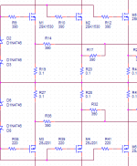
R10=390 and R39=220, see below! I'm sorry, but it is really your schematic.
How about your glasses?
edit: Is the photograph of your amp supposed to be a replacement of a schematic? Not the most efficient and accurate way to exchange design ideas.
syn08 said:1. Take a deep breath.
2. Put your glasses on (if applies).
3. Open this: http://www.diyaudio.com/forums/showthread.php?postid=1596058#post1596058
4. Look careful at the picture and try to identify the gate resistors. Hint: they are close to the 2SK1530/2SJ162 gate pins. If you don't know which is the gate pin just ask.
5. Identify the gate resistor values. A magnifier can come handy.
Now you can rest and continue to elaborate brilliant ideas. Meantime, you may want to recall how many times you posted or otherwise published schematics with some errors.
R10=390 and R39=220, see below! I'm sorry, but it is really your schematic.
How about your glasses?
edit: Is the photograph of your amp supposed to be a replacement of a schematic? Not the most efficient and accurate way to exchange design ideas.
Attachments
Edmond Stuart said:Regarding the closed loop BW of a HEC-OPS vs. a NFB-OPS, there are no essential differences. They both have the same kind of caveats.
There is an important difference from a practical point of view. For a conventional feedback OPS, the bandwidth is constrained to be approximately the same as the ULG frequency. For an HEC stage, the bandwidth has no such constraint. It's instead constrained to be approximately the same as without HEC - normally a much higher number than the achievable ULG frequency of a feedback OPS.
Granted, its distortion will be no better (and maybe somewhat worse) than a conventional FB amp with the same ULG frequency, but its bandwidth will typically be appreciably higher. This has implications when it's placed inside of the feedback loop of the amplifier as a whole.
- Status
- This old topic is closed. If you want to reopen this topic, contact a moderator using the "Report Post" button.
- Home
- Amplifiers
- Solid State
- YAP - Yet Another PowerAmp