Hi Chris,
Your thinking on multi turn pots is flawed. Bias circuits can sometimes pass a large enough current through the base lead of the transistor. Don't assume it's next to nothing.
Multiturn controls are very poor choices for bias setting controls. If you want to reduce the adjustment range, then vary the series resistance and the resistance from base to collector. Then you will have a reasonable adjustment.
Re: bias current and playing with it.
If you use a distortion analyzer and adjust the bias, you will see a null. That is the one true and proper adjustment. There is zero need to play with this adjustment past this setting.
Try this.
-Chris
On the average though. . .the bias current is low. . . .the whole
purpose of the transistor is to control a small current through the
base thus larger current through the emitter(amplify)? When I did
some tests and calculations the current through the bias trimpot
was in the microamp range. . . it will vary beyond the idle amount
but not more than 6dB.
I agree that there is a small range that produces the minimum distortion in an amplifier and that will be the correct bias. But
we are DIYers. . . the fun is trying. . . otherwise we would live
in the world of "Brazil" where the bureaucracy fixes the problems
or causes them.
Anatech, I fully respect your knowledge of electronics.
A Case for Multi-Turn Potentiometers in Bias Circuits
A Case for Multi-Turn Potentiometers in Bias Circuits
The max (be) voltage for the 2SD600 is -5V.
R619 and VR601 are in the (be) circuit path.
If R619 is a 1/4W 2.7kohm, then 25.98V/9.62mA is the max for R619.
Also VR601 will never have more than 9.62mA through it.
9.62mA is the max current through the R619+VR601 path; thus the
max current to be drawn through the VR601. If the VR601 were set
to 2.2kohms then 203mW of power will be dissapated; more often the
VR601 will be set to some lower value, thus less power dissapated.
This is a worst case seniero.
I measured VR601 in the 600mV range when setting the idle current;
that would be 273microA through 2.2kohms and 6mA through 100 ohms.
If the wipper was to go to 1 ohm then 600mA would flow. . .but R619
would be long dead and open.
I don't think that the currents involved in this circuit would be
detrimental to multi-turn pots.
With modifications to the circuit.
R619 = 3.58kohm
VR601=500ohm
Then1/4W R619 can have a max current of 8.3mA, thus VR601 will
only have the same max current in worst case situations before
the R619 self distructs. If VR601 were set to 500 ohms, then
8.3mA would be 4.15V and 34mW; when VR601 is set to 200 ohms,
then the power drops more than half (1.66V/14mW). In normal
bias condition the voltage drop is more like 600mV across 300ohms,
so the current is near 2mA (1.2mW).
Again, this low level of current in this type of circuit will work for
many decades. . . power dissipation is also well within spec
for the multi-turns.
Re: A Case for Multi-Turn Potentiometers in Bias Circuits
After reviewing my notes more closely that 600mV was the
total voltage across R619 and VR601.
The real voltage across the VR601 was in the range of
160mV to 200mV.
Left and Right Channels differ and bias set spec at 4mV to 14mV.
The VR601 ranged from 900ohms to 1300ohms(3dB):
160mV/1300ohms=123microamps
160mV/900ohms=177microamps
200mV/1300ohms=153microamps
200mV/900ohms=222microamps
It would take a 13dB gain in current to reach 1mA!
Even with the new circuit with R619=3.58kohm, if the VR601
shorted out. . . the bias could only go up to less than 30mV or
136mA through each output resistor.
I measured VR601 in the 600mV range when setting the idle
current; that would be 273microA through 2.2kohms and 6mA through
100 ohms.
After reviewing my notes more closely that 600mV was the
total voltage across R619 and VR601.
The real voltage across the VR601 was in the range of
160mV to 200mV.
Left and Right Channels differ and bias set spec at 4mV to 14mV.
The VR601 ranged from 900ohms to 1300ohms(3dB):
160mV/1300ohms=123microamps
160mV/900ohms=177microamps
200mV/1300ohms=153microamps
200mV/900ohms=222microamps
It would take a 13dB gain in current to reach 1mA!
Even with the new circuit with R619=3.58kohm, if the VR601
shorted out. . . the bias could only go up to less than 30mV or
136mA through each output resistor.
Hi Chris,
It's the base current in the VBE multiplier you should be calculating, this is what passes through the moving contact.
Your range of control is far too wide. If you allow the VBE multiplier to turn off, the amp goes boom. It does this in Technicolor and Cinemascope. Complete with stereophonic sound. Your adjustment range will always keep the VBE multiplier in it's active range. There is no reason the circuit can not be designed with a restricted but useful range.
-Chris
It's the base current in the VBE multiplier you should be calculating, this is what passes through the moving contact.
Your range of control is far too wide. If you allow the VBE multiplier to turn off, the amp goes boom. It does this in Technicolor and Cinemascope. Complete with stereophonic sound.
Your adjustment range will always keep the VBE multiplier in it's active range. There is no reason the circuit can not be designed with a restricted but useful range.-Chris
Hi Chris,
It's the base current in the VBE multiplier you should be calculating, this is what passes through the moving contact.
I set the bias to 4mV on both channels.
The 2SD600+R618+R620+VR602 is the Vbe multiplier.
(with a constant current source).
I measured the voltage across R620 = 552mV
I measured the voltage across R620+VR602 = 615mV
The voltage potential across the base+emitter of 2SD600 is 615mV.
R620=3.58kohm = 154microamps
If 154microamps is flowing through R620, then it is flowing through
VR602 also.
VR602 voltage: 615mV-552mV = 63mV
Thus VR602 resistance is: 63mV / 154microamps = 408 ohms
Only 154microamps flows through the moving contact in spec mode!
Your range of control is far too wide. If you allow the VBE multiplier to turn off, the amp goes boom. It does this in Technicolor and Cinemascope. Complete with stereophonic sound.
The original circuit had a 2.7kohm + 2.2kohm trim-pot = 4.9kohm
which was more than enough to shut down the bias. Which when
the trim-pot was set to 0 ohms was enough to run the bias up
to over 50mV.
The new circuit is a 3.58kohm + 500ohm trim-pot = 4.08kohm
This is a much smaller range with an upper limit almost 900 ohms
less than the original circuit. . . and a minimum resistance higher
than the original lowest resistance. . .the amp cannot go past
30mV bias now. It would be difficult to shut the bias down since
the upper resistance limit is 900 ohms less than the original design.
The control range of the new circuit is far less wide than the original.
Your adjustment range will always keep the VBE multiplier in it's active range. There is no reason the circuit can not be designed with a restricted but useful range.
I agree. I think we are in agreement? All except the multi-turn pot.
I think it could be stated.
A multi-turn pot will require more maintenance in the future.
(due to DC current is detrimental to the small contact area)
A multi-turn pot will give higher precision adjustment of bias.
A single turn pot will give longer service life.
(due to a larger surface contact area)
A single turn pot will give lower precision adjustment of bias.
(exposed contact area can get dusty and imprecise)
Anatech and I will probably never agree on this subject. He has
seen more multi-turn pots in for service and seen the detrimental
effect of them in circuits with DC current.
I am willing to suffer the hair pulling of a multi-turn pot going
intermittent and replacing it; I want the precision--and with it,
suffer the ill effects.
I think I stated my position. This is a great discussion. . .
Attachments
Re: Yamaha M-80
Sorry everyone I have been so busy that I havent even been
into diyaudio for at least a month.
i would be happy to share the materials on these amps.
they sure arent doing me any good.
there are about 50 pages some of which are foldouts, there are also somewhat legible notes on some pages that i wrote during the class.
Maybe I could scan some of the parts of most interest and share them. sounds like many of you already have a service manual
cporter said:[
I was also hoping amp-guy might be willing to part with his design and trouble shooting guide. [/B]
Sorry everyone I have been so busy that I havent even been
into diyaudio for at least a month.
i would be happy to share the materials on these amps.
they sure arent doing me any good.
there are about 50 pages some of which are foldouts, there are also somewhat legible notes on some pages that i wrote during the class.
Maybe I could scan some of the parts of most interest and share them. sounds like many of you already have a service manual
Hi,
Gni,
Let me chime in.
If you have altered the adjusting range of your pot to be something more manageable instead of something like simply "on-off" within a few degrees. Why would you then need a multiturn pot?
If find it hard to talk about "ten turns of precision" here. The bias circuit overcompensates for changes in temp.
Adjust bias as good as you can, then play loudly for a minute, then immediately check bias again.....same? No.
gni said:This is a great discussion. . .
Gni,
Let me chime in.
If you have altered the adjusting range of your pot to be something more manageable instead of something like simply "on-off" within a few degrees. Why would you then need a multiturn pot?
If find it hard to talk about "ten turns of precision" here. The bias circuit overcompensates for changes in temp.
Adjust bias as good as you can, then play loudly for a minute, then immediately check bias again.....same? No.
I am beginning to agree that the high precision of the multi-turn
is unnecessary in this type of amplifier. Especially since I've narrowed
the range of adjustment. Sometimes I just need to try something to
see how it works. . . Anatech will win this round! Will be reverting
to a standard turn pot of 500 ohms.
Big Cheers!
I still need some adjustment since each channel requires alsmost
100 ohms difference on the trim-pot. I did think for a while of just
dropping a close enough resistor in an letting it fly. A little 'control'
freak voice inside my head just couldn't let go.
Hi Chris,
There is no round to win. I am only concerned with this myth propagating. However, you have seen what the main point is as far as adjustment range is concerned.
I can accept were you are coming from too. You need proof to see another side, and that's fine. Yamaha was always bad for leaving far too much range in their controls. A shoot from the hip fix would be a multiturn control. The main problem with that is not many people will research the parts they use.
Hi amp-guy,
Your notes would be interesting to read. You (and me for sure) are never too old to learn more.
-Chris
The Yamaha does have too much range. . .I won't be digging into
that amp too much. . .
I'll put is simply: You scared the hell out of me about multi-turns.
Also,
I've seen the result of the multi-turn in an operating amplifier. . .it
really didn't make that much difference. . . the bias still drifts some
percentage. . . 0.1mV here or there isn't going to matter. . .things
heat up and cool down. . .there is a certain amount of flex.
I did some research on the Vbe multiplier circuit. . . some bad
things do happen when it fails to operate properly. . . depending
on which resistor dies open or closed. Scary.
Hi Chris,
Just wait until you open an amplifier to find visibly bad solder joints on all heat sink mounted parts. That has made my mouth run dry on more than one occasion.
-Chris
This is the nature of the beast.I did some research on the Vbe multiplier circuit. . . some bad
things do happen when it fails to operate properly. . . depending
on which resistor dies open or closed. Scary.
Just wait until you open an amplifier to find visibly bad solder joints on all heat sink mounted parts. That has made my mouth run dry on more than one occasion.
-Chris
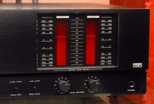
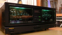
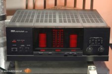
Yamaha Meters were cool
Welcome DanTana,
I really loved the sound of the Yamaha M-series from the 80s. . . fun as hell to mod. . .lots of space. I've only one working M-45 out of my two original. I'm down to one channel sadly. . .but it still has great sound. My other unit was gutted and made into a four channel amp with the meters working for two of the four channels; dual power supplies for the amps and a third for the meters. Blue LEDs for the power indicator. . .listen to your great amp before it dies. . .they all do. . .and they really just don't make them like they used to(they don't sound as good either). I hope to install a tube amp in the carcass of the working amp when it finally dies. . .headphone jack and subwoofer (150Hz) line level output. It is just fun to watch those Yamaha meters pumping away. . .they best lightshow meters (the old Kenwood Basic M2A is a great second and Onkyo had some great analog needles! Carver had some fun analog meters too.)
Chris
Attachments
Last edited:
- Status
- This old topic is closed. If you want to reopen this topic, contact a moderator using the "Report Post" button.
- Home
- Amplifiers
- Solid State
- Yamaha M-80 Mods FINISHED! GOLD!!!