Banned
Joined 2002
When adjusting the bias on any yamaha amp you should let it sit for about 20 min with no speaker connected. I moved my pot 1/16th of a turn till the amps both had the same voltage acrosss the power resistor's.. I was not going to pay 100$ for the manual. Till this day it's still working.
BIAS - A strange new world...
Hafler... Takes 20+ minutes to level out. Yamaha manual says to wait 2 minutes (hah!) I found it levelled in around 5, but waited 10 to make shure.
Although quite stable, sparkling new bias pots would be a nice addition... (hehehe... uh oh... now I've got that itch to tinker again)...
"Auto class A" is a nightmare. I've heard a lot of stories from people with the M series that have had trouble, or that it doesn't work correctly. Seems to work by magic, if it in fact works.
I found that the reason one channel was running hotter than the other, was that the auto class A was only boosting bias only on that side. And yup, from the corrected 10mv only went up to about 80mv, not 130.
Another thing to put on my "to-do" list will be to disable the Auto A switch, and probably just hard bias the amp as high as the pots will allow evenly... probably only 15~20mv. Most likely will still stay super cool too. Definitely very safe if the Auto A was supposed to be pushing 130. Couldn't notice a difference between the channels anyway.
Will have to use some of my grey-matter to figure a way to possibly hard-bias maybe at 40 or 80mv, as a nice comprimise between heat and performance. 40mv feels like a good number, keeping things stress free.
Sounds like a great job on the ole Yammie. I have the ability to pick one of these up locally really cheap, and have a few questions that maybe someone could help with.
If I do get the M80 I would definately perform some mods to it. The 3 speaker relays you mentioned earler: I'm assuming that they are triggered by the speaker selection switches? I don't have the schematics, but hopefully will soon.
I guess my final question is: Would you rate this an an "audiophile" (sound quality) amp, and might it compare favorably to stuff like B&K, Aragon, etc. I am currently running SAE A202. The SAE's are nice, but entirely too bright with my apogees.
Thanks,
Brian
Hi, the M-80 is one of the best amp that was produced in those years
and have a great value on today's market.For my point of vue, you'll have to pay at least $4000.00 (today and new)for a amp as good as this one.If you have the chance to grab one cheap, go ahead and buy it.I will put mine on ebay soon because I have no use for it and it's just sitting on a table doing nothing so I will let someone else play with it.
Just let me know if you need some shemes to help you restoring it.
I have to agree with Ostie01 as it was one of the top amps in it's days. I'd value it less, but mainly just due to parts that have critically aged. I had been looking at the Rotel lineup as a similar replacement, but think the Yammy might still be smoother sounding, and more overbuilt (gigantic heatsinks) in certain aspects, but sucks in a few others. Still, good value for the money these days.
Probably the best you can get for bright speakers; keeping fatigue at a minimum with no lack of detail. Definitely not audiophile grade, due to some bad design choices, but can be brought up a grade when modded. Nothing wrong with the way they work though, a very comfortable listening amp.
Probably the best you can get for bright speakers; keeping fatigue at a minimum with no lack of detail. Definitely not audiophile grade, due to some bad design choices, but can be brought up a grade when modded. Nothing wrong with the way they work though, a very comfortable listening amp.
Upgrade Overload
Whaaaaaa, just had the urge to dive back in.....
1-Shot, 14 straight hours, no breaks, total concentration, no rushing, and complete success.
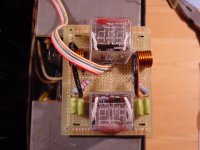
1) Built my own custom relay board, with some relays I had picked up. Hand calibrated the contact pressure, and cut the middle pole (3P relay) so there would be better pressure balance. Prayed that they'd get enough juice to drive them... The prayers worked. Mounting is much more reliable now that I could make proper holes.
2) Bypassed the Auto-A switch. Why have 2 bias resistor feeds travel through 2 feet of wiring??? And leave it open ended when switched on? Unreliable. Stated idle bias should be 10mv, Auto-A 130mv (seems to only do about ~80mv for the amps it actually works on), I set the idle to 40mv... gets lightly warm, but nothing extreme; probably more stable than the Auto-A would ever be too. A good balance.
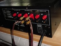
3) Used heavier wiring from the relays to the posts, Used 12G for the ground and 16 for the outputs. Anything thicker won't fit. 12G is pretty much the limit for soldering.
4) Changed the power cord to a 14G heavy-duty one. Found a great gasket to fit it. Just needed to grind the hole a bit bigger. A modular socket would have been way too much trouble.
5) Wired directly: the power cord to the switch (+fuses) and transformer lines. Removed the wire wrapping posts, and soldered the power wires directly in.
6) probably did more, but it's all a great blur now....
Last things to consider doing...
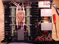
- Redo the core wiring; No. Yamaha used heavy copper wire for the signal and normal steel for feedback. Decent job, not worth changing. Was easily able to reduce some length on the final output-to-relay section.
- Power/Cap board wirewraps; maybe hard solder. BUT the huge smoothing caps make the underside inaccessable. The wirewraps are very well done anyway. Maybe could solder the wirewraps, but no apparent need.
- Precision pots for the bias; Yeah. I picked up some presicion single-turns, didn't install them. Multi-turns would be better for this amp. The bias can swing from 0 to 200mv+ (I didn't try any higher) with a simple 1K pot. Yeek, big swing! But the original pots seem to hold stable when worked with to the get value you want.
- Transformer vibration gaskets; No. After some poking, they still seemed soft. The tops of the transformers could easily be affixed to a piece of polycarbonate or aluminum with hot glue or acoustic adhesive to add a bit more dampening. Easy to do this anytime.
- really nothing more necessary... Yay!
Final Notes:
- Yamaha schematics seems to be more of a guideline. Some parts aren't installed. Sometimes part order differs (manual: cap-resistor-cap, reality: resistor-cap-cap). Best to follow how the amp was actually made, and add your own touch.
- Yamaha uses audio ground for the chasis. And there is no way to get around this (in order to switch it to earth-ground) as almost every mainboard mounting hole grounds to the chasis. Not a biggie, but I prefer chasis earthing for safety.
- The gold plated Yamaha relays are 4 pole and rated at 5A per, that's why they doubled up the connections. Slightly unreliable, as I had noticed 1 of the poles had some arcing damage. Better to use a simple 2pole 10A type....
- Since this worked, and I didn't set the house on fire, It was quite a fun project.
Whaaaaaa, just had the urge to dive back in.....
1-Shot, 14 straight hours, no breaks, total concentration, no rushing, and complete success.
1) Built my own custom relay board, with some relays I had picked up. Hand calibrated the contact pressure, and cut the middle pole (3P relay) so there would be better pressure balance. Prayed that they'd get enough juice to drive them... The prayers worked. Mounting is much more reliable now that I could make proper holes.
2) Bypassed the Auto-A switch. Why have 2 bias resistor feeds travel through 2 feet of wiring??? And leave it open ended when switched on? Unreliable. Stated idle bias should be 10mv, Auto-A 130mv (seems to only do about ~80mv for the amps it actually works on), I set the idle to 40mv... gets lightly warm, but nothing extreme; probably more stable than the Auto-A would ever be too. A good balance.
3) Used heavier wiring from the relays to the posts, Used 12G for the ground and 16 for the outputs. Anything thicker won't fit. 12G is pretty much the limit for soldering.
4) Changed the power cord to a 14G heavy-duty one. Found a great gasket to fit it. Just needed to grind the hole a bit bigger. A modular socket would have been way too much trouble.
5) Wired directly: the power cord to the switch (+fuses) and transformer lines. Removed the wire wrapping posts, and soldered the power wires directly in.
6) probably did more, but it's all a great blur now....
Last things to consider doing...
- Redo the core wiring; No. Yamaha used heavy copper wire for the signal and normal steel for feedback. Decent job, not worth changing. Was easily able to reduce some length on the final output-to-relay section.
- Power/Cap board wirewraps; maybe hard solder. BUT the huge smoothing caps make the underside inaccessable. The wirewraps are very well done anyway. Maybe could solder the wirewraps, but no apparent need.
- Precision pots for the bias; Yeah. I picked up some presicion single-turns, didn't install them. Multi-turns would be better for this amp. The bias can swing from 0 to 200mv+ (I didn't try any higher) with a simple 1K pot. Yeek, big swing! But the original pots seem to hold stable when worked with to the get value you want.
- Transformer vibration gaskets; No. After some poking, they still seemed soft. The tops of the transformers could easily be affixed to a piece of polycarbonate or aluminum with hot glue or acoustic adhesive to add a bit more dampening. Easy to do this anytime.
- really nothing more necessary... Yay!
Final Notes:
- Yamaha schematics seems to be more of a guideline. Some parts aren't installed. Sometimes part order differs (manual: cap-resistor-cap, reality: resistor-cap-cap). Best to follow how the amp was actually made, and add your own touch.
- Yamaha uses audio ground for the chasis. And there is no way to get around this (in order to switch it to earth-ground) as almost every mainboard mounting hole grounds to the chasis. Not a biggie, but I prefer chasis earthing for safety.
- The gold plated Yamaha relays are 4 pole and rated at 5A per, that's why they doubled up the connections. Slightly unreliable, as I had noticed 1 of the poles had some arcing damage. Better to use a simple 2pole 10A type....
- Since this worked, and I didn't set the house on fire, It was quite a fun project.
Attachments
yamaha class a amps
Hi Bluesmoke:
back when the Yamaha M-80 and M-60 amps came out
I attended a yamaha service seminar on these amps.
Honestly I dont remember much about them , it has probably been 20 years since I have seen one.
But I do have a tutorial on their design and a troubleshooting
guide .
it is probably around 50 pages worth.
and is arguably the best written I have seen.
wow... hey... this thread is still movin'
Had sold the amp after a bit, feeling like I wanted to move on to a new project. Took a painful loss on it though... was in too much of a silly rush.
stepping into the way back machine...
bhostinsky: (2006)
- yup, used the speaker switches to control the new relays. Same voltage, at touch more current was needed I think, so I didn't use the resistors that were on the old DEC relays. I think the original main panasonic relay was resistor-free.
- wouldn't think of this as an audiophile amp, however it is a very good "listening" amp (laid-back, detailed but mellow sounding). Best of the period for a mass product. Invisible noisefloor, enough power to drive anything well. When biased properly, can drive 4~ohms without burning up. Compared to some other amps I've heard with a higher damping factor, the Yamaha could have used a touch more control in the bottom end. Upgrading the relays and output wiring did seem to help a bit. Have no way to measure though if there was a real improvement.
amp-guy: (2007) today
- would have been neat to attend the seminar. I was a bit nervous to dig inside the amp, but wasn't really difficult to isolate the areas that needed work. The schematic really helped. Big thanks to ostie01 for that. If a transistor popped, or some other sensitive component, it would be a paperweight since I don't know how to test/work on deep internals.
M80 service manual
Blue smoke,
I came across your post about the M80 tricks. I have 2 and you have inspired me to do just what you did. Would you recomend replacing all of the input and output transistors and caps or is there some other components that should be replaced. I am not real electronic savy but I believe I have enough skills too pull this off. Ireally like what you did with the speaker terminals and relay board. If you would happen to have a service manual you could forward that would be of great help.
Thank you,
tom s
Hi Tom,
Do not replace the outputs, you're asking for trouble there. Replacing any other transistors will guarantee a broken amp. These were pretty good at the time and you have two. Consider yourself lucky. I used to repair them under warranty.
You can replace the speaker terminals. In truth, I don't think it will do more than make you feel good. The originals are not that bad compared to the spring terminal types. New speaker relays would help more, use the same type to make things easy on you. If you must use different relays, make sure they fit. If you can't, then make a new PC board properly. Place the components where they originally were (copy the old board with the new relay pin spacings and pin out). Try and mount it where the old one went.
New filter caps might be a good idea, do not increase the value. You may find it worthwhile to replace the smaller electrolytic caps on the boards. That will improve the sound quality.
Get the service manual, Yamaha does not charge a lot for them. I think around $20 is about right (in Canada anyway). Make sure you are looking at the US/Canada version. Other versions are a little different.
10 turn bias controls are a waste of time and not recommended. The single turn controls are fine, but Yamaha had a habit of having too much range. That means adjustment can be touchy. We called it "Yamaha syndrome". Thicker power cord is a waste of time on this one. Also, do not run the bias too hot. If you want to defeat the bias switch - okay. Just don't crank the bias way up. It does no good at all. "Class A" bias was a marketing deal.
-Chris
Banned
Joined 2002
SO in theory, your stating just leave it alone if it is workinganatech said:Hi Tom,
Do not replace the outputs, you're asking for trouble there. Replacing any other transistors will guarantee a broken amp. These were pretty good at the time and you have two. Consider yourself lucky. I used to repair them under warranty.
You can replace the speaker terminals. In truth, I don't think it will do more than make you feel good. The originals are not that bad compared to the spring terminal types. New speaker relays would help more, use the same type to make things easy on you. If you must use different relays, make sure they fit. If you can't, then make a new PC board properly. Place the components where they originally were (copy the old board with the new relay pin spacings and pin out). Try and mount it where the old one went.
New filter caps might be a good idea, do not increase the value. You may find it worthwhile to replace the smaller electrolytic caps on the boards. That will improve the sound quality.
Get the service manual, Yamaha does not charge a lot for them. I think around $20 is about right (in Canada anyway). Make sure you are looking at the US/Canada version. Other versions are a little different.
10 turn bias controls are a waste of time and not recommended. The single turn controls are fine, but Yamaha had a habit of having too much range. That means adjustment can be touchy. We called it "Yamaha syndrome". Thicker power cord is a waste of time on this one. Also, do not run the bias too hot. If you want to defeat the bias switch - okay. Just don't crank the bias way up. It does no good at all. "Class A" bias was a marketing deal.
-Chris

Hi,
Things look easier if you don't know what you are getting into. I also know the effects of some of the changes that were talked about.
-Chris
And what would you recommend?I am not real electronic savy but I believe I have enough skills too pull this off.
Things look easier if you don't know what you are getting into. I also know the effects of some of the changes that were talked about.
-Chris
Hi cporter,
Not enough information given.
I will assume the amp was repaired under your insurance policy? They have not completed the repair. Did you take it to an authorized Yamaha warranty center? If not, that is where it should have gone. If so, complain to the service manager.
So, the usual questions come to mind. Can you let us know what your experience and equipment availability is? Do you have the service manual?
-Chris
Yamaha M-80
I've some experience repairing electronics that I acquired while working on my EE degree. Right now I don't have easy access to a O-scope, signal generator or a regulated DC power supply however.
I took the amp to a place in Dallas that used to be THE authorized service center. Found out they're under new management and not the authorized service center after they worked on it for several weeks. They replaced/repaired several items and said they had gotten to the point where everything worked right while the protection circuit was defeated...
Since they didn't get it repaired he just charged for the diagnosis and I had him throw in the service manual as well. It's missing page 9, the meter schematics. Looking at the schematics there is nothing labeled as the protection circuit and that may be on the missing page.
So my purpose for posting was two fold:
Reduce my learning curve by checking with people that have worked on the M-80 amps. If you know that the protection circuit schematics are on the missing page or if you can point out the inputs and outputs to it that would help. Knowing what input signals produce triggering functions would also be a help.
I was also hoping amp-guy might be willing to part with his design and trouble shooting guide.
It was stated earlier that the 'Class A' on the Yamaha units was
a marketing ploy. It seems that the bias voltage jumps when
engaged: creating a nice space heater. I've often thought of
disabling the switch and using it for a fan on/off. Just set the
bias and leave it then.
I have a copy of a M-60 service manual. . .from the DIY threads I think.
a marketing ploy. It seems that the bias voltage jumps when
engaged: creating a nice space heater. I've often thought of
disabling the switch and using it for a fan on/off. Just set the
bias and leave it then.
I have a copy of a M-60 service manual. . .from the DIY threads I think.
- Status
- This old topic is closed. If you want to reopen this topic, contact a moderator using the "Report Post" button.
- Home
- Amplifiers
- Solid State
- Yamaha M-80 Mods FINISHED! GOLD!!!