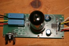
I've built this YAHA but can't get to work. 
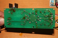
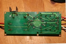
There is power going to the board but absolutely nothing happens. The bottom side is kind of messed up from changing some components when it didn't work.
I'm hoping someone can spot something that I'm missing and it's not another screwed up project
There is power going to the board but absolutely nothing happens. The bottom side is kind of messed up from changing some components when it didn't work.
I'm hoping someone can spot something that I'm missing and it's not another screwed up project
Attachments
I thought R5 was optional. It's not on the photo of the finished amp.
Pretty sure it is on that photo. It's just not mounted on the board - it's one of the two resistors hanging in the air next to the tube socket.
Also, I'm really not sure about that "mod" to the heater supply described in your PDF. The original YAHA article has this set up as a 300mA constant current supply. With the "mod" described in the first schematic in your file, it seems to represent a 1.5V voltage supply. That doesn't seem great to me, just like the resistor values are mixed up or something (do wait for a more qualified opinion on that though before randomly swapping parts - but the wiring diagram above the photo in your PDF seems to confirm my suspicion).
edit: Also, I think the red lines in the wiring diagram are meant to be wire jumpers. (some of those extra holes can also hold the R7/C3 mod) Those are not connected on your board at all! So, for example, your tube cathode isn't grounded, but completely floating.
edit2: The silkscreen on your PCB also seems strange. The slot that says R2L (next to the caps) would be the perfect place for R1R, and indeed the wiring diagram in the PDF seems to suggest that R1R should go there. (but from cap to ground, so you're still one hole off) That description/schematic/board/etc is just very inconsistent.
Last edited:
Looks like omitting the wire jumpers is your main problem, or at least a major problem. You can see the one that's straight out from pin 7 of the op amp, in the photo in the PDF, but not in your photo. And I assume that all of the other red lines in the diagram in the PDF are also supposed to be wire jumpers.
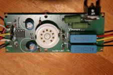
You still don't have R5/R6 right. It seems that the PCB you have is meant for the original regulator configuration as designed by fa-schmidt, which uses a single 4.2 Ohm resistor in the position marked R5 on your board and NO R6. The reason there are two slots (R5 and R5') on your PCB is most likely that you can parallel resistors to get close to 4.2 Ohm or distribute heat dissipation between two resistors.
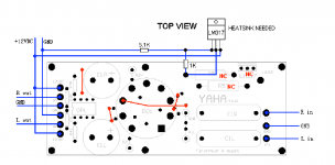
If you want to build the amp as described in your PDF (with a voltage regulator with R5/R6 as in the 'mod' schematic), follow the wiring diagram! I have copied it for convenience. In there, "NC" means "not connected", the regulator is not mounted on the board, and R5 only has one leg in the PCB. Also be careful with your wire jumper on the bottom of the board, that one looks suspiciously like it's not isolated and touches another tube pin!!
If you want to build the amp as described in your PDF (with a voltage regulator with R5/R6 as in the 'mod' schematic), follow the wiring diagram! I have copied it for convenience. In there, "NC" means "not connected", the regulator is not mounted on the board, and R5 only has one leg in the PCB. Also be careful with your wire jumper on the bottom of the board, that one looks suspiciously like it's not isolated and touches another tube pin!!
Attachments
Last edited:
I think there's still a misunderstading:
- Avro Arrow is talking about Pin 3 on the LM 317, which is still disconnected and so doesn't provide anything to the heater.
- I'm saying that if you want to go with the "mod", you have to follow the wiring diagram. Simply removing the second R5 in your current configuration won't help, even if you fix the problem mentioned by Avro Arrow.
You could try either, but don't try to mix them! It's not really your fault, the PDF you have is not consistent between its schematics, diagrams and pictures. I think the easiest option from where you are now is to follow the wiring diagram (i.e. the picture that I attached to my previous post #14).
- Status
- This old topic is closed. If you want to reopen this topic, contact a moderator using the "Report Post" button.
- Home
- Amplifiers
- Headphone Systems
- YAHA HELP