Yes. Both have good bass. But FR has much more detail and infinitely more air.
Ah yes, I forgot to post this! A pretty authoritative endorsement for single caps in the signal path.
Re: Paralleling caps- are there any "rules" - aurphon - Tweakers' Asylum
Ah yes, I forgot to post this! A pretty authoritative endorsement for single caps in the signal path.
Re: Paralleling caps- are there any "rules" - aurphon - Tweakers' Asylum
Last edited:
Interesting stuff there great thanks sharing shootout steelarelephant.
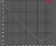
Below is impedance sweep for one Panasonic FR 6800uF and same sweep with added parallel PP film 10uF looks exactly the same so there is no clue to see inside low bandwidth that DATS unit is covering.
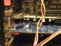
Also think FC series are great value and good sound, below is M-Audio AP192 soundcard having original 22uF exchanged with 470uF that because of volume needs to sit on other side of PCB, the use of relative higher value help improve HD when measured and also when soundcard is used as measure device there is much less excess phase finding place at lows so that measured absolut phase is much more in agreement with theoretical minimum phase.
Below is impedance sweep for one Panasonic FR 6800uF and same sweep with added parallel PP film 10uF looks exactly the same so there is no clue to see inside low bandwidth that DATS unit is covering.
Also think FC series are great value and good sound, below is M-Audio AP192 soundcard having original 22uF exchanged with 470uF that because of volume needs to sit on other side of PCB, the use of relative higher value help improve HD when measured and also when soundcard is used as measure device there is much less excess phase finding place at lows so that measured absolut phase is much more in agreement with theoretical minimum phase.
Attachments
Last edited:
Capacitors galore...
XRK, what are the absolute maximum dimensions for 4 electrolytic capacitors on the top layer while still fitting into a tin? Am I correct in assume you could potentially fit two 12.5mm by 20mm power supply capacitors and two more 12.5mm by 25mm output capacitors lying horizontally across the board?
The ones I'm thinking of using are:
The power supply capacitor I found referenced earlier, however the audio output capacitor was just the FR series (which I seem to be reading is the recommended output capacitor versus the original oscon/film) datasheet's largest 16V value that matched diameter and length restraints. (I have seen a picture online of Elna Silmic 470uF 16V, which are 12.5mm by 25mm being successfully fit as output coupling, but with 10mm diameter power supply capacitors).
Also, is there any consensus as far as bypassing the input (JFET Rin is absurdly large so it shouldn't matter but the 47k+270 highpass bothers me), output, or power supply capacitors on the other side of the board?
Sounds like the best choice are two 1000uF FR's in parallel for deep bass and resolving highs.
Ok, I will order me some 1000uF FR's with next batch of caps.
XRK, what are the absolute maximum dimensions for 4 electrolytic capacitors on the top layer while still fitting into a tin? Am I correct in assume you could potentially fit two 12.5mm by 20mm power supply capacitors and two more 12.5mm by 25mm output capacitors lying horizontally across the board?
The ones I'm thinking of using are:
- Output Coupling: Panasonic FR 2700uF 16V
- Power Bypass: Panasonic HD 2200uF 25V
The power supply capacitor I found referenced earlier, however the audio output capacitor was just the FR series (which I seem to be reading is the recommended output capacitor versus the original oscon/film) datasheet's largest 16V value that matched diameter and length restraints. (I have seen a picture online of Elna Silmic 470uF 16V, which are 12.5mm by 25mm being successfully fit as output coupling, but with 10mm diameter power supply capacitors).
Also, is there any consensus as far as bypassing the input (JFET Rin is absurdly large so it shouldn't matter but the 47k+270 highpass bothers me), output, or power supply capacitors on the other side of the board?
fiddled a bit more with my LiIon batteries (Soshine brand).
Either the protection circuit is more aggressive than you guys' EBLs or my capacitors are too large at 2700uF. It will never charge it sufficiently to turn on even with flicking it on and off many times.
Needs a "jump start" from either an alkaline or another power source. Starting it with 1x liion + 1x alkaline charges the caps, and i can quickly switch to liion and it works. If you guys know another way I'm all ears.
The two power rail caps lying sideways is max 13mm dia x 20mm long. That's a 2200uF 25v if you can find it.
For output bypass on through hole side (actually the "bottom"), the biggest in size is the Silmic II 100uF 16v which is 10mm dia x 13mm long. There are holes for two sets, but room for three sets of six total along width of board. The extra two could have legs bent 90deg and soldered to legs of others that go through. For sheer capacity, the 1000uF 16v OSCONs is tough to beat. It sounds quite fantastic in my opinion - and also opinion of others who have reviewed. Like the Headfonics review had 1000uF OSCONs plus 470uF AK's. I have had several dual 1000uF OSCONs with 10uF Silmic bypass receive excellent reviews as well. On input a 10uF Silmic fits where Wima is and leave it at that. Or just 2.2uF Wima by itself is fine.
For output bypass on through hole side (actually the "bottom"), the biggest in size is the Silmic II 100uF 16v which is 10mm dia x 13mm long. There are holes for two sets, but room for three sets of six total along width of board. The extra two could have legs bent 90deg and soldered to legs of others that go through. For sheer capacity, the 1000uF 16v OSCONs is tough to beat. It sounds quite fantastic in my opinion - and also opinion of others who have reviewed. Like the Headfonics review had 1000uF OSCONs plus 470uF AK's. I have had several dual 1000uF OSCONs with 10uF Silmic bypass receive excellent reviews as well. On input a 10uF Silmic fits where Wima is and leave it at that. Or just 2.2uF Wima by itself is fine.
The two power rail caps lying sideways is max 13mm dia x 20mm long. That's a 2200uF 25v if you can find it.
For output bypass on through hole side (actually the "bottom"), the biggest in size is the Silmic II 100uF 16v which is 10mm dia x 13mm long. There are holes for two sets, but room for three sets of six total along width of board. The extra two could have legs bent 90deg and soldered to legs of others that go through. For sheer capacity, the 1000uF 16v OSCONs is tough to beat. It sounds quite fantastic in my opinion - and also opinion of others who have reviewed. Like the Headfonics review had 1000uF OSCONs plus 470uF AK's. I have had several dual 1000uF OSCONs with 10uF Silmic bypass receive excellent reviews as well. On input a 10uF Silmic fits where Wima is and leave it at that. Or just 2.2uF Wima by itself is fine.
The layout I was referencing in my post was this one:

Those brown Silmics are 12.5x25, however he's using 10mm diameter power supply capacitors. Do you think 12.5mm diameter supply capacitors would fit? 12.5x25 output coupling capacitors might open up further options for output caps in a portable version of this amp.
Last edited:
You could probably squeeze 12mm dia power rail caps in there. Best way to tell is to try it. Unless you feel like building a 3D car model to do it virtually.
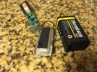
I tried it (four horizontal 12.5mm wide caps) and couldn't fit my OKCell 9V batteries in the tin, because the rail caps were protruding past the edge of the board. But maybe it is possible with different batteries or a different brand of mint tin?? One possibility I'm considering is to pop those LiPo batteries out of their cases which makes them half the size (see pic), or try my hand at doing a DIY battery like X has done.
Another option I may try on another build down the road is to omit the battery wire socket and just solder battery wires directly to the PCB on the SMD side. This would free up space for longer rail caps. Panasonic FR has a 10x25mm can size that would fit there. For instance, I would really like to try that fat Silmic that Funch used on output, with a 25V 1200uF FR on the rails.
Attachments
Last edited:
Look for a 51mm x 52mm x 7.8mm 2600mAhr LiPo batterymodel number 785251 on eBay. They are about $10. You will have plenty of room for a 3x2200uF RCRCRC (use 0.47R 1W) filter plus D.C. Step up plus USB charger module.
Li-polymer Rechargeable Battery 3.7V 2600 mAh Li-Po ion 785251 for Tablet PC | eBay
MT3608 Step Up Power Supply Module DC-DC 2V-24V to 5/9/12/28V Adjustable c0z | eBay
Plus USB charger circuit.
10 x TP4056 1A Lipo Battery Charging Board Charger Module lithium battery DIY
You now have all the parts you need to make a pretty long lasting battery system.
Look for a 51mm x 52mm x 7.8mm 2600mAhr LiPo batterymodel number 785251 on eBay. They are about $10. You will have plenty of room for a 3x2200uF RCRCRC (use 0.47R 1W) filter plus D.C. Step up plus USB charger module.
That's definitely an interesting option. I really like the fact that it allows micro USB charging for the amp, but the total stored energy is about the same as two 600mAH 8.4V batteries... and there's the added noise of the DC boost converter to deal with - which the gained room in the tin provides a solution for. Have you tried these little DC boost converters for audio, I assume they're pretty noisy, no?
I am using one now and it's dead quiet. Even without the RCRCRC it's not audible - I only have it to make the measurements pretty. The FFT is posted a ways back - it's essentially flat -123dB noise floor similar to regular batteries.
The DC step up is at 1.2MHz, so noise is easily filtered at band band.
The DC step up is at 1.2MHz, so noise is easily filtered at band band.
Thanks for the links to parts, X! You set your step up to 16.5V, right? And so your three caps in the filter are 16V rated? If I set mine to 18V, can I substitute, say, 1500uF 25V caps, or is the 2200uF value a critical spec?
And, a noob question: does higher voltage from the battery have the exact same effect as tweaking bias via R4 value?
And, a noob question: does higher voltage from the battery have the exact same effect as tweaking bias via R4 value?
Interesting. Thanks.
This amp is incredible. While cooking dinner tonight I hooked up my second PCA build as a preamp for my Tripath->Aurasound kitchen boombox. It has never before sounded even close to this good! Even my wife, who is known to roll her eyes at my audio endeavors and is constantly heckling me about my "flux capacitors" actually said..."This is the most I have enjoyed listening to music in a long time." When I took the PCA out of the signal chain and went direct from my DAP into the boombox, she said, "It sounds so flat!"
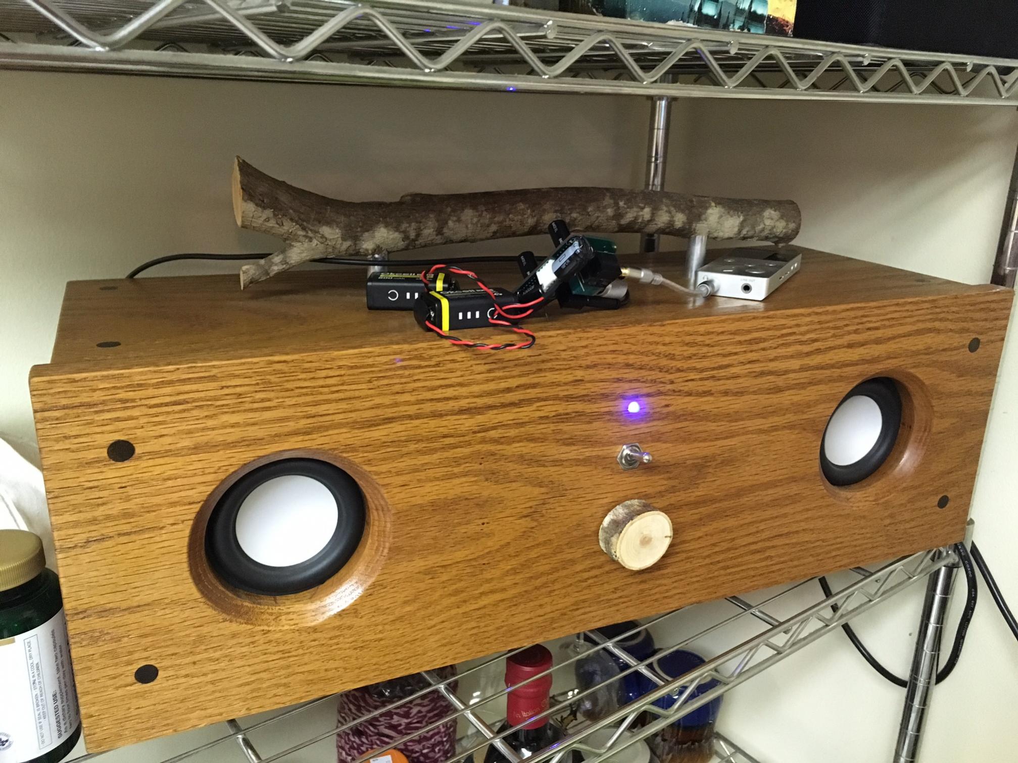
While my first build made substantial improvements to the same system in terms of dynamics and presence, this one makes strides across the board. Heftier bass, clearer treble detail and instrument separation, wider imaging (still not that wide...it's just a boombox!), and punchier dynamics than I ever expected to get from a 3.5" driver. Speed, presence and realism are all improved with this PCA in the chain.
I'm just astounded at the difference a clean, powerful Class A signal can make. X, you're the man for sharing this mighty little amp design. I encourage you to try out the stacked PPS & Panny FR cap combo. I think you'll agree that these transparent caps just get out of the way and allow the transistors to sing beautifully! At the moment I'm in the mood to build one of these for every audiophile I know...
This amp is incredible. While cooking dinner tonight I hooked up my second PCA build as a preamp for my Tripath->Aurasound kitchen boombox. It has never before sounded even close to this good! Even my wife, who is known to roll her eyes at my audio endeavors and is constantly heckling me about my "flux capacitors" actually said..."This is the most I have enjoyed listening to music in a long time." When I took the PCA out of the signal chain and went direct from my DAP into the boombox, she said, "It sounds so flat!"
While my first build made substantial improvements to the same system in terms of dynamics and presence, this one makes strides across the board. Heftier bass, clearer treble detail and instrument separation, wider imaging (still not that wide...it's just a boombox!), and punchier dynamics than I ever expected to get from a 3.5" driver. Speed, presence and realism are all improved with this PCA in the chain.
I'm just astounded at the difference a clean, powerful Class A signal can make. X, you're the man for sharing this mighty little amp design. I encourage you to try out the stacked PPS & Panny FR cap combo. I think you'll agree that these transparent caps just get out of the way and allow the transistors to sing beautifully! At the moment I'm in the mood to build one of these for every audiophile I know...
Attachments

Last edited:
I've been saying all along that I don't listen to my regular Class AB amps without this as preamp anymore.
Now I understand why... After I finish this portable build, I plan to build a SMPS-powered desktop version to live inside the boombox. Brings the thing to life!
Now I understand why... After I finish this portable build, I plan to build a SMPS-powered desktop version to live inside the boombox. Brings the thing to life!
Into these pre test stage think if its possible add a switch to drivers wiring that can switch their polarity to counter for PCA inverts, because some drivers in free air or in their final loading system end up when tested with advanced klippel-tests not to be perfect symmetrical in push/pull performance, admit for OB-1 that A/B tests for polarity was transparent for my ears but for some speakers have experienced noticeable difference whether polarity follow standards.
I must have missed something further back. This amp flips the signal polarity? So I should reverse my speaker wiring?
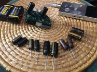
Beginning my final round of tin-sized cap listening tests.
25V 220uF Cerafine / 16V 330uF Cerafine / 25V 470uF Cerafine / 16V 220uF Silmic / 25V3 30uF Muse
I should have also gotten the 16V 470uF Silmic that Funch used, but forgot that one. Even so, I think I'll get a good idea of the pure Silmic sound, just with a tiny bit less bass.
Attachments
Last edited:
I must have missed something further back. This amp flips the signal polarity? So I should reverse my speaker wiring?...
It inverts and that can be reason or not why she said "It sounds so flat!" without PCA, but it should be easy to experiment for in try without PCA and a flipped speaker wire, or with PCA and a flipped speaker wire.
Also to have PCA HD profile as into post 1 then don't load it lower than 270 ohms, myself tested it at 32 ohms and picture is very different then.
...Beginning my final round of tin-sized cap listening tests.
25V 220uF Cerafine / 16V 330uF Cerafine / 25V 470uF Cerafine / 16V 220uF Silmic / 25V3 30uF Muse
I should have also gotten the 16V 470uF Silmic that Funch used, but forgot that one. Even so, I think I'll get a good idea of the pure Silmic sound, just with a tiny bit less bass.
Nice arsenal there : )
- Home
- Group Buys
- xrk971 Pocket Class A Headamp GB