![WP_20170330_007[1].jpg](/community/data/attachments/564/564538-c790069451bf48b37e59fa4025af311e.jpg)
No no, mic inputs with Limp: NOOO!
The XLR connectors are MIC inputs, while the Line/Inst inputs are jack connectors.
I don't think you can use a Mic Input for one channel and a Line Input for the other one. Maybe it's what makes the calibration derail. You must use the 2 Line/Inst Inputs. Check the manual!
Btw you have only measured one channel, and you need to check both.
Last edited:
merlin el mago, I am not familiar with the ARTA/Limp system and GDO may be pointing you in the right direction of solving your variable measurements. I found this site which is very informative Index of /06_Lit_Archive/15_Mfrs_Publications I would think that building the Limp measuring box to the indicated version is your next step and having an amplifier that acts as a buffer and can supply the power for both the impedance and frequency response applications is part of the setup requirements. I could not discern from your posts if an amplifier ( or brand ) is in use.
No need to use a power amp with Limp, unless you wish to perform T/S param measurments at high excitation levels. For standard measurements at 100mv or alike the phone outputs of the uca202 are enough, and for measurements at 1V or similar i use the more powerful RME fireface uc from its headphones output.
No power amp needed for any small signal measurements and above.
No power amp needed for any small signal measurements and above.
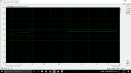
FR all loudspeaker mic 1 meter + high pass filter 500Hz for SS8545 in green without high pass filter 500Hz for SS8545in yellow mic situated in th middle of all drivers.


Any suggestions to improve the xover?
An externally hosted image should be here but it was not working when we last tested it.
Any suggestions to improve the xover?
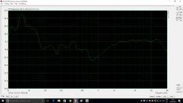
mic same position yellow SS8545 green SBA
An externally hosted image should be here but it was not working when we last tested it.
Doesn't look bad at all...
Now consider that under 1khz measurements made in room at 1 m, with drivers close to the floor, back wall and side wall need to be interpreted rather than taken as the holy bible...
The big bump around 1khz is probably due to wall reflections, but what you see is extremely dependant from the position from which measurements are done, so that i personnally would not care too much about those things.
I would rather now move the mike to your prefered listenning position, 2m or 3m, or whatever and make the same measurements to see what your room curve looks like, as if you were measuring for DRC.
Or do you prefer sterile discussions about measurments and CAD...
Last edited:
ok but what xover is this? The high passed SS or the other one?
Anyway it is clear that it will be tough to get a balanced sound whatever good or bad the xover.
May be try to play some music and comment...
Also try to change SS polarity to check what happens to the deep at 500-1000hz...
Anyway it is clear that it will be tough to get a balanced sound whatever good or bad the xover.
May be try to play some music and comment...
Also try to change SS polarity to check what happens to the deep at 500-1000hz...
- Status
- This old topic is closed. If you want to reopen this topic, contact a moderator using the "Report Post" button.
- Home
- Loudspeakers
- Multi-Way
- Xover to filter woofer SB 23NRSX45-8