The temperature sensor is build it into the battery. There is not connected, as then the charger system it may become much complicated. The actual charger is set it up for a quite low charging current (not needed fast charging at all), and the charger chip it monitor/protect quite well the charging process.
The battery never ever increase its temperature in this set up (verified). Also this charger type is widely used in this respect, and it works very safe.
The battery never ever increase its temperature in this set up (verified). Also this charger type is widely used in this respect, and it works very safe.
Last edited:
You can never guarantee that with lithium ion batteries, and for safety it is always best to use a dedicated charger IC for safety reasons, such as:
http://datasheets.maximintegrated.com/en/ds/DS2710.pdf
With the recent scares regarding Li batteries and chargers you can never be to careful, just saying, as all Li based designs I have worked on have the extra safety built in just to cover all eventualities even with low current trickle chargers, and if you sell this product you will then be party to the relevant safety standards in the countries where the product is shipped, such as UL for the USA.
A UL Li safety guide:
http://www.ul.com/global/documents/...ty Issues for Lithium-Ion Batteries_10-12.pdf
DS2710 chip is a single cell NiMH battery charger. Her is about LiIon battery, and not only one cell, as the mobile phone batteries are. So, not suitable in this case.
The cell phones batteries are sold world wide and it cover the safety regulations. The same the chargers based on the chip used in this project.
If it will be sold this board, then it will be sold without battery and oscillators mounted on it. As these components are up to the user`s applications and needs.
Just an example device...just saying as we face these issues with regards to ever increasing demands for safety in products every day on a wide variety of projects. And while there may be some over-reaction, there has been some problems with Li batteries and it is always best to cover your self as much as possible with regards to safety, especially with the USA, where class action law suits are thrown around like confetti.
hi
my essence stx has channel imbalance between left and right, I just discovered today, I was blaming my dsp but I realized the issue is causing from STX.
The only mod on this card I did is upgrading to Audio-gd JZ-1 TCXO clock.
The right channel have slightly more treble than left, but left channel has bold and flatter and louder sound than right. Stereo imaging is left focused. I can hardly handle the issue with balance adjustment of the STX driver.
Can anybody have an idea to fix this weird issue ?
Your board it may be defective when about the post processing DAC circuits... You should take a look at the opamp stage, its output, verify the +/-12v rails.
It should be interesting to know if this issue was present before replacing the clock oscillator. .. Harmonics in oscillator frequency it may produce such disturbance.
BTW, there is not necessary to use sophisticated oscillator circuits in this case. There is not so much place anyway on the board. A better component/oscillator chip is enough to increase the sound quality. The standard board do not use an oscillator, but a resonator which control the oscillator inside the board`s processor. This is one of the big problems of Asus sound cards. I can see it were corrected in the last edition of ST/STYX II.
Your board it may be defective when about the post processing DAC circuits... You should take a look at the opamp stage, its output, verify the +/-12v rails.
It should be interesting to know if this issue was present before replacing the clock oscillator. .. Harmonics in oscillator frequency it may produce such disturbance.
BTW, there is not necessary to use sophisticated oscillator circuits in this case. There is not so much place anyway on the board. A better component/oscillator chip is enough to increase the sound quality. The standard board do not use an oscillator, but a resonator which control the oscillator inside the board`s processor. This is one of the big problems of Asus sound cards. I can see it were corrected in the last edition of ST/STYX II.
No this issue did not present before clock upgrade
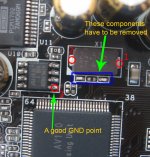
, may I be damaged the caps around the resonator chip while removing it?OK, that is the problem... You should remove all the components around the old resonator chip. There are two resistors and two small ceramic caps. Just clean the place there where the resonator it was. Make sure you inject your clock signal into the pin nr 46 of the processor. The processor accept clock signal from both 5v or 3,3v oscillators.
The clock signal path it have to be as short as possible. No more than 10mm. In your case, as the clock generator is quite big, you should use a thin coax cable to transport the clock signal. GND point of the clock signal (coax shield) it have to be very close to the processor GND pin/chip.
The clock signal path it have to be as short as possible. No more than 10mm. In your case, as the clock generator is quite big, you should use a thin coax cable to transport the clock signal. GND point of the clock signal (coax shield) it have to be very close to the processor GND pin/chip.
Last edited:
OK, that is the problem... You should remove all the components around the old resonator chip. There are two resistors and two small ceramic caps. Just clean the place there where the resonator it was. Make sure you inject your clock signal into the pin nr 46 of the processor. The processor accept clock signal from both 5v or 3,3v oscillators.
The clock signal path it have to be as short as possible. No more than 10mm. In your case, as the clock generator is quite big, you should use a thin coax cable to transport the clock signal. GND point of the clock signal (coax shield) it have to be very close to the processor GND pin/chip.
hi chris I thank you so much for helping me.
I actually not know so much about electronics, when I look at the board, I see there small things just below the resonator. so should I remove all of them?
And the other thing I want to tell you that there are big nichicon caps above the resonator, I touched them a few times accidentally with solder iron. should I replace them?
I may say that proceeding to such clock mod on this board, one need some basic knowledge and informations about how to be done it...
You should remove the old resonator, and the components around it (previous post). There are informations in this thread, and by googling.
You do not need to replace the Nichicon caps if they are not destroyed. But I can not know their status, and how much heat they had to endure...
You should remove the old resonator, and the components around it (previous post). There are informations in this thread, and by googling.
You do not need to replace the Nichicon caps if they are not destroyed. But I can not know their status, and how much heat they had to endure...
Hi again coris
I think you misunderstood me, I alrady removed old resonator but the resistors and caps still there, and I am not using the pin nr 46 on the processor, I just injected the clock to the old resonator's pin.
Here is the picture what I did.

so should I remove components you mentioned, and inject the oscillotar freq directly to the pin nr46 of the proc. ?
I think you misunderstood me, I alrady removed old resonator but the resistors and caps still there, and I am not using the pin nr 46 on the processor, I just injected the clock to the old resonator's pin.
Here is the picture what I did.
so should I remove components you mentioned, and inject the oscillotar freq directly to the pin nr46 of the proc. ?
Hi recepky
There is a nice installation of your clock. Else is a little bit difficult to be seen what is on the board, because of the light reflections.
Yes, you should remove the old components around the former resonator (resistors and caps). These components do not have any function as far as the resonator is gone. It only disturb the clock signal from the new oscillator...
You can use the corresponding resonator pad (if it still be there) to inject/connect your new clock output. You may follow the trace which goes from pin 46 to the resonator pad, and use that pad to connect your clock. There is more convenient to use that pad instead the pin of the processor. Extremely care may be taken if you are force to use the processor pin... I do hope is not the case.
hi coris
I removed those two resistors and ceramic cap, they are very very small, it was a hard operation
result is interesting again, stereo image now focused on the center but, I feel like right channel has a little little bit more treble than left
but I must say that the stereo image is clearer than before.
I removed those two resistors and ceramic cap, they are very very small, it was a hard operation
An externally hosted image should be here but it was not working when we last tested it.
An externally hosted image should be here but it was not working when we last tested it.
result is interesting again, stereo image now focused on the center but, I feel like right channel has a little little bit more treble than left
but I must say that the stereo image is clearer than before.
Hi recepky
I see in your last pictures that you use a coax, but to be honest I think is a little bit wrong way to use this cable...
As you can see, this coax cable it have a central wire, and a shield over on it. This shield is meant to be used too, and is to be always connected to a GND point. I can not see that you did so, out of your pictures...
This is quite important to not alternate the clock signal. This coax is not to be used for power connections.
So, please locate the output of your oscillator device. Near to that output pin/point it should be a GND point too on your oscillator. Use these pins and connect the signal from the oscillator output to the centre of the coax cable, and the GND point (on your oscillator) to the shield of the same coax. On the other end of the same cable (to the sound card), connect accordingly the clock to the old resonator tab, and the shield of the coax to the GND point (pointed in my last picture). Then find another wire to connect the power of your oscillator to the output pin of the 5v 7805 regulator.
This way it should be right to make connections in this case. Then you can give it a try to the music...
It seems to me that you use another power supply for your clock. You may keep in mind that your eventual extra PSU for the clock it have to have the same GND as the sound card. The GND point (or minis pin) of your oscillator it have to be connected to the sound card GND. If you will use the coax in the right way, then everything it will be all right. You will need only a third wire to connect the +V of the oscillator to the right place.
Last edited:
hi coris
I thinked about how to use this coax shield but I couldnt figure it out, but your solution look clever. I will try it,
but as you may already know or I dont understand the power connection you advice. this clock has class a psu that requires 10-24VDC so I am feeding this clock one of the molex cable out of my computer power supply.
Just got my transformer for my project...
It's center tapped, but looking at the wiring layout...one of these pairs should be negative AC, correct? Doesn't say which...
Both inputs can be paired to 110VAC together, correct, to output + and -, or this is how I understand it.
Any feedback would be appreciated.
It's center tapped, but looking at the wiring layout...one of these pairs should be negative AC, correct? Doesn't say which...
An externally hosted image should be here but it was not working when we last tested it.
Both inputs can be paired to 110VAC together, correct, to output + and -, or this is how I understand it.
Any feedback would be appreciated.
- Home
- Source & Line
- PC Based
- Xonar ST/STX mods...