Thanks Coris...
Looks as if my 1.02 also had a switching PSU on board as well.
If one was to inject -12V regulated at u34 (?), the unregulated -12V first has to be removed from the design...do you see a way of doing this?
I think if you remove the molex power and add external 12V to the 7812, then the -12V would also get power...?
Sent from my iPhone...
If you want to inject your power rails for analogue stage, then you may remove accordingly the ferrite beads to isolate the old ones. The Molex and its power it have to be intact and connected, as the old switching PSUs it must work further (unloaded). These PSUs are controlled in one way, by the card`s software/processor. Errors in the driver of the board occur if the switching PSUs +/- 12v stop function.
Coris would you plese reply to post 439
also what do you think about that mod MAKING A DECENT HI-FI POWER SUPPLY FOR XONAR ESSENCE - Page 19
also what do you think about that mod MAKING A DECENT HI-FI POWER SUPPLY FOR XONAR ESSENCE - Page 19
If you want to inject your power rails for analogue stage, then you may remove accordingly the ferrite beads to isolate the old ones. The Molex and its power it have to be intact and connected, as the old switching PSUs it must work further (unloaded). These PSUs are controlled in one way, by the card`s software/processor. Errors in the driver of the board occur if the switching PSUs +/- 12v stop function.
Okay...so where do I want to add external power then? At pin 3 of the 7812 and where the 7912 was designed to go?
Do you have a pic of the beads that have to come off?
Thanks!
Sent from my iPhone...
Coris would you plese reply to post 439
also what do you think about that mod MAKING A DECENT HI-FI POWER SUPPLY FOR XONAR ESSENCE - Page 19
Post 434...
Okay...so where do I want to add external power then? At pin 3 of the 7812 and where the 7912 was designed to go?
Do you have a pic of the beads that have to come off?
Thanks!
Sent from my iPhone...
I do hope the pic here by can explain....
Attachments
I do hope the pic here by can explain....
Nice! Thanks!
It looks like the diode would be the easiest to unsolder....?
Where is your ground connected to the board? I think my regulator has separate grounds for the - and + power...would it be best to connect my reg grounds to the center pins of the 7812 and 7912 spots (or the big case pad).
And to be sure, you DO still need the +12 and +5V molex connected even after adding -+ external power?
This is great! Ordering the parts for my reg board this weekend and my low jitter clock with discrete power is on it's way.
Just need to find a good linear/analog AC/DC PSU now.
Sent from my iPhone...
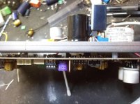
You may connect together the GND of the positive regulator with GND of the negative one and solder the common ground as shown in picture.
In the same point it should be also connected the whole GND of your new double PSU (mid point of the transformer, the GND of the filtering caps, GND of the regulators. The connection have to be shortest as possible, using a quite big section wire.
As an inspiration, I show here too the picture of my previous moded STX with the external PSU on the back of the board...
Attachments
Coris you have made lot of hard work with that heavy duty PSU
on the previous shot from you - the points where are Inserted +12 and -12 rails are all that card needs excluding 3,3 V , Is that correct
the power for 5V supply Is regulated from Inserted positive 12 V ?
so 5 V power for Analog to Digital Convertors Is regulated from shown Inserted power points ?
I have to do sampling vinyl and that Is why I am Interested how can I proper supply Input digital part
Well, I have to make some clarifications...
First is not about to insert +/-12v from a external PSU, but +/-15v. This power is required by the opamps I used to work properly. Most of opamps are specified for these tensions.
Second (I have to repeat), the board need the Molex connector to be connected, as nothing is changed. Else errors in software occur.
Third, the +/-12v or 15v are also used in the ADC stage of the board. I did not exterminated closer what is the impact of some changes in power rails for the ADC stage. I just was/are not interested in this. My goal were/is to get the best sound out of the board (playback). So, those who want to use the ADC stage, have to be carefully and analyse more deeper the consequences of mods on the sound card.
Something else, also important.
The +/-rails for analogue stages on the board, are exclusively dedicated to this task (dual power for opamps which need this). These rails should not be used to regulate/generate some other lower rails for the board. Dedicated power it should be used for this proposes. Why? Regulate or using more current from a rail in a dual powering system it will unbalance the rails, generate ripple and noises. This is actually the clue with external power to feed this board: give to the circuits the best power needed, with no compromise for economical reasons.
So, as a conclusion: dedicate dual power to opamps which need this, provide special/dedicated power for another rails, as 3,3v, 5v, or else, from a separate power source (separate winding of the transformer).
Use correctly the grounding on the board. Digital ground is designed to be different than analogue one. It have to be like this, so just care about when connect your power system. Placing/inserting the new power rails and its GND pole, on the old filtering caps terminals, it may be a right way to do it, to have the right ground connections as the designers decided.
Special care have to be accorded to right connecting of the GND in between power system and the boards circuits. Wrong ways to do it it may compromise the whole project... and noises can increase and make the sound card unusable.
Else, one can play with the 3,3v or 5v rails as one want, so far these rails are provided from a dedicated winding of the main transformer. Filtering these rails and regulated it in cascade it may improve the noise levels on outputs. One can very well use the 12v from Molex to regulate it to a 8v, and then to 5v, and/or 3,3v. The 12v rails from the computer is not as bad to be used for digital stages, but quite noisy for analogue stages... So, this rail it should be used accordingly...
Special care it may be taken when about the oscillator/clock power system. Use dedicated regulator for any oscillator, or (better) battery power only for these devices.
My last mod of a new sound card is based on isolating the whole power for DAC and its analogue stage, and feed it with a carefully designed power system. Again, I`m not interested in input stage of the card (ADC), so I will not use time to focus myself in this area. For me, if this part of the board will not function, I just do not care...
I do hope these clarification will help one to take the right decisions, when proceed to mods on this board. Even though some informations here and there about the subject, I have to say that this task is not easy, skills, tools and knowledge are needed to do it right, and minimise the risks.
If one do not own basic knowledge in electronics, should not proceed to such demanding tasks as modding a quite complex designed product. The result it may be right opposite than wished...
Last edited:
I'd love to hear more about your PSU...
Did you build that one yourself? I'm still a little fuzzy on the grounding...
You connected your ground to both - leads of those caps, or is just the one fine? They seem to be in series...?
Also, my injected power source will already be regulated, using this...
I'm gonna go with you and set it up for -+15V...
Will the 5V regulation on the board (for DAC) be powered from this rail or from the 12V from the molex?
I was thinking a 7812/7808/7805 cascade from my regulated 15V to feed this...because I haven't thought about an external PSU yet!
Sent from my iPhone...
Did you build that one yourself? I'm still a little fuzzy on the grounding...
You connected your ground to both - leads of those caps, or is just the one fine? They seem to be in series...?
Also, my injected power source will already be regulated, using this...
An externally hosted image should be here but it was not working when we last tested it.
I'm gonna go with you and set it up for -+15V...
Will the 5V regulation on the board (for DAC) be powered from this rail or from the 12V from the molex?
I was thinking a 7812/7808/7805 cascade from my regulated 15V to feed this...because I haven't thought about an external PSU yet!
Sent from my iPhone...
I'd love to hear more about your PSU...
Did you build that one yourself? I'm still a little fuzzy on the grounding...
You connected your ground to both - leads of those caps, or is just the one fine? They seem to be in series...?
Also, my injected power source will already be regulated, using this...
An externally hosted image should be here but it was not working when we last tested it.
I'm gonna go with you and set it up for -+15V...
Will the 5V regulation on the board (for DAC) be powered from this rail or from the 12V from the molex?
I was thinking a 7812/7808/7805 cascade from my regulated 15V to feed this...because I haven't thought about an external PSU yet!
Sent from my iPhone...
Well, well...
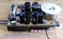
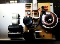
Your PSU it may be good, but how it looks its PCB is quite huge... To be honest, I do not think one may use such complicated (regulated) PSU for this task. If you will use a double PSU for the whole board, then is not needed more than 300mA per rail. If you use the PSU only for the DAC analogue post processing, then the needed currents are under 100mA. A very small (easy) toroid transformer will deliver enough power for the task. A rectifier bridge per rail, filtering caps, some +/- quite ordinary adjustable regulators will be enough to get a good double PSU for the propose. Yes, I have build it by my self that PSU on a prototype PCB, as you may see in the picture. As I sayd, my PSU is enough complicated because I designed it to switch the power on battery use, then control all the system when the batteries should be empty, and so on... Quite complicated. It works well for me, but normally, one may not need all these things. Just a simple double regulated PSU placed as near as possible to the sound card. The shortest ground connection is very important to get good results...
I have used a steel plate to have a mechanical platform for it, and a good magnetic isolation for the transformer. with some spacers I have used the existing holes on the sound card to mount the metal plate on it.
Do not forget the mechanical aspects when about an external PSU (like you intend to build). The whole system it may fit the place inside your computer enclosure. If you think to have your external PSU outside the computer, it may not be very fortunate... because the quite long connections involved
There are some standard dimensions inside a computer, one may care about to not come in conflict with another devices/boards. There is not very much place anyway. The whole sound card system may not create mechanical tensions when the card is in its PCI/PCPIex slot in the mother board. It have to be not heavy at all. This is quite important to not destroy the motherboards delicate traces/connections.
So, one may think at quite many aspects when start a such project...
Else, the caps I refereed previously are serial connected between the +/- rails of the board. It is enough to connect the GND of your PSU on one leg of the caps, where they are connected to the board GND plane. It have to be only one short connection in only one point on the ground from your PSU and the sound card.
The 5v rail for DAC I have made it from 12v Molex rail. Regulated to 8v, and then to 5v to avoid the big gap between 12v and 5v which produce enough heat dissipation on 5v regulator. Doing so there is not need of a heatsink for 5v regulator, and the cascade regulation improve the performances. If you go to use the 3,3v from PCI slot, then it may be quite simple. If you think to create 3,3v for DAC digital stage, then you may use your 5v rail (as above) to regulated it down to 3,3v...
One more information about these original +/- 12v rails on the sound card.
These rails are created using PWM circuits (or something like this) which are controlled in one way by the main DSP/processor on the board or another dedicated circuits. This double 12v PSU do not start if the board do not get the 3,3v power. On +12v rails is to be measured only 5v and -12v rail shows only a nice square (0 to -12v) wave if one only power the board from Molex connector. As the board is in its slot and get the 3,3v rail, everything become normal in this area.
So, this power system on this sound card is not very simple at all...
I just only wonder why the Asus designers did not created +/-15v for the analogue stages, as this it could be very easy, and should leads to better performances for the opamps used.
Last edited:
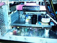
Some more pictures of my (earlier) modded sound card (and the last edition - pic 3), as inspiration for those interested...
Attachments
Last edited:
My regulator board is sophisticated, yes...and large. But I might be able to use a lower quality external PSU to feed it, and let the regulator smooth and regulate the power.
Perhaps even a 20V/4.5A laptop power brick? Integrate a relay for power up in sync with the PC...?
The 5V regulation on the STX would be fine enough for now that I'll just leave it be...
Your pics are indeed inspirational!! Awesome work!!
This thread would be no where without your contribution Coris...it's very much appreciated, especially when you consider you having to hold the hand of a rookie like myself!!
Thank you
Sent from my iPhone...
Coris
thank you for shots
Is your last edition psu regulator better than older - It looks simpler I guess It Is a serial regulator are you using LM317 and LM337
what about shunt regulator
I like Noratel trafos very much but consensus Is that EI type and particular r core and split bobbins are better - Hammond and Block making last mentioned
what type are your caps are they Pana FC
Last edited:
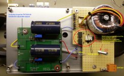
Two possible solution (suggestions) for high quality external PSU for the sound card analogue stage. For dimensional comparative the STX is pictured too... Else everything else of standard/common regulators are enough good in this case. Do not forget a solid filtering...
I will suggest using of toroid transformer, as they radiate minimal magnetic field, and are very efficient for this propose. Shielding of the transformer is beneficial for even better (noises) results.
I will suggest using of toroid transformer, as they radiate minimal magnetic field, and are very efficient for this propose. Shielding of the transformer is beneficial for even better (noises) results.
Attachments
Last edited:
Coris
thank you for shots
Is your last edition psu regulator better than older - It looks simpler I guess It Is a serial regulator are you using LM317 and LM337
what about shunt regulator
I like Noratel trafos very much but consensus Is that EI type and particular r core and split bobbins are better - Hammond and Block making last mentioned
what type are your caps are they Pana FC
The last edition of my PSU it were designed thinking to a battery use too. That because it looks quite complicated. Else the main PSU has minimal changes than the older one.
That my last PSU allowed me to switch on the fly between wall and battery power for the sound card, so I could very well appreciate the eventual changes in sound quality. I have to say that is no sound difference in using a battery to power the board analogue stage, than a normal serial PSU. That because I`m thinking now to improve even more my concept, using one of the above suggested solutions...
It were interesting for me to get +/-15v out from the original PWM PSUs on board, and then appreciate the results. Unfortunately, the negative PSU on my board did not want function any more after I have changed the resistor in it, to get a higher tension level...
Last edited:
Hey Coris...
Since I invested so much time/money with my regulator board, what would you think about using, for example, a laptop power brick to feed the regulator?
It's crappy (switching?) power, but 20V and up to 4.5A...
The regulator board should be able to use it and clean it up.
I'd hook it up inside the case (shielded from mainboard/soundcard) and switch it with a relay off the PC's PSU.
My regulator will except AC input as well, so maybe just a simple transformer? (Something I don't know a whole lol about except they step up or step down)
Sent from my iPhone...
Sorry to say, but I will do not ever think at a such solution with a computer PSU...
First there is about a switching PSU, which this project main idea is to eliminate it from get in to the analogue stage of this sound card. Second, a such PSU is very noisy for audio use. Third, this kind of PSU have quite heavy start up currents. Very much care is to be taken to soft start a such PSU. But all of all, my opinion is at a laptop PSU is definitely not to be used in this field.
You can sell further your big PSU, or use it in another project... Some very good double serial regulators cost no more than 20$, or the more complicated one, 100$ (as pictured above). these are quite small and fit very well the sound card area.
If you may put together by your self some components (schematics are plenty to be founded on net), on a prototype PCB, it may be a more cost effective solution, very efficient in this case.
Very soon I will come out with some more pictures of my going project. So you may see some other solutions for this mod...
Anyway, you should use an normal transformer (toroidal) to power your regulator, and do not ever think at a laptop power brick...
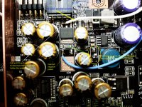
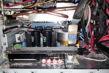
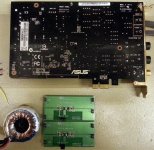
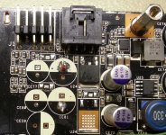
I show here a solution to place an external double PSU for the analogue stage of the DAC (opamps). In this case the double PSU is only to feed the DAC analogue stage, and not for whole board.
A double PSU for whole bord (DAC/ADC) may take around 200mA. My PSU here is dedicated to feed only the DAC opamps (max current 150mA)
I think the pictures do not need more explanations...
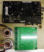
As one can see, there is a clue to have this double PSU as near as possible to the board (very short GND connections). A good place for such PSU is right on the back of the board. In this case it is a claim to have pass through places in the sound card to transfer the +/-V and GND from the PSU to another side of the board, to the modded DAC and its analogue post processing circuits.
To solve this problem is to find two places on the board which it may be completely isolated from the rest of the board, with a common ground point with the board ground plane. This solution is only suitable in case one may not want any more the +/- on board PSUs. This is a mod is for advanced modders...
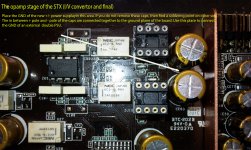
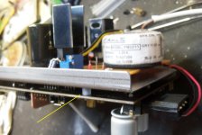
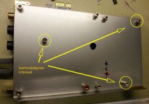
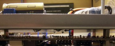
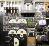
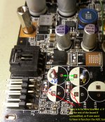
If one remove some components as shown in the pic1, get one access to such isolated points with through holes for wires. In pic2 one may see the soldered through wires for +V, -V and GND. Pic 3 shows another angle of the mounted pass through.
In this illustrated case here, the ADC stage of the board does not function. If one may use a double PSU which it may deliver at least minimum 300mA, and insert this power in right points (shown on the pic 3), then is possible to power the ADC stage too. So, be aware about this detail in this mod presented here....
A double PSU for whole bord (DAC/ADC) may take around 200mA. My PSU here is dedicated to feed only the DAC opamps (max current 150mA)
I think the pictures do not need more explanations...
As one can see, there is a clue to have this double PSU as near as possible to the board (very short GND connections). A good place for such PSU is right on the back of the board. In this case it is a claim to have pass through places in the sound card to transfer the +/-V and GND from the PSU to another side of the board, to the modded DAC and its analogue post processing circuits.
To solve this problem is to find two places on the board which it may be completely isolated from the rest of the board, with a common ground point with the board ground plane. This solution is only suitable in case one may not want any more the +/- on board PSUs. This is a mod is for advanced modders...
If one remove some components as shown in the pic1, get one access to such isolated points with through holes for wires. In pic2 one may see the soldered through wires for +V, -V and GND. Pic 3 shows another angle of the mounted pass through.
In this illustrated case here, the ADC stage of the board does not function. If one may use a double PSU which it may deliver at least minimum 300mA, and insert this power in right points (shown on the pic 3), then is possible to power the ADC stage too. So, be aware about this detail in this mod presented here....
Attachments
Last edited:
- Home
- Source & Line
- PC Based
- Xonar ST/STX mods...