Thanks Coris... You've been a big help in figuring out my D2.
I have a couple more questions:
If my JRC's are dual channel, how come 2 are used (as in one for left, one for right)? Or are these the buffers, and the National chip is the main channel.
Also, seems like the capacitors are only used with the single chip/channel, not the pair (2X JRC 2114's)
Look at the pics of my caps (above), are these values .22uF and .1uF?
What values would you suggest for replacements?
Sent from my iPhone...
Oh...another question.
If I say run a separate regulator board, at 10V+ and 10V-, could I power it with the computers PSU with 12V+ and 5V+ coupled to get 17V+ using blocking diodes on each rail to prevent 17V travelling back towards the PSU on each rail?
Thanks!
Sent from my iPhone...
If I say run a separate regulator board, at 10V+ and 10V-, could I power it with the computers PSU with 12V+ and 5V+ coupled to get 17V+ using blocking diodes on each rail to prevent 17V travelling back towards the PSU on each rail?
Thanks!
Sent from my iPhone...
Thanks Coris... You've been a big help in figuring out my D2.
I have a couple more questions:
If my JRC's are dual channel, how come 2 are used (as in one for left, one for right)? Or are these the buffers, and the National chip is the main channel.
Also, seems like the capacitors are only used with the single chip/channel, not the pair (2X JRC 2114's)
Look at the pics of my caps (above), are these values .22uF and .1uF?
What values would you suggest for replacements?
Sent from my iPhone...
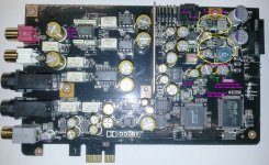
As you can see on the board there are 4 DACS. This mean 8 channels. Two of these it may be the main stereo/front channels.
The all opamps used are dual amp chips, but this does not necessary mean one amp is used for one audio channel, and another for the second.
One DAC use 3 of dual amps opamps. Two of these opamps are I/V converters for 2 audio channels. These I/V converters use two amps per audio channel. The final opamp, which convert differential to unbalanced output, use the inside amps for each audio channel (L/R).
Is quite easy to see on the board that each DAC chip is further connected to 3 opams. Near the DAC are the I/V converters, then it follows in the middle, the final opamp which is surrounded by the white film caps (8,2n/22n).
This circuit is common for all 4 DACs.
The I/V opamps have too some caps (ceramic) around it. But the biggest film caps are around the final opamps.
I personally do not like these caps in the signal path. Less caps/capacity in the signal path, better (higher fidelity) for the outputted signal. These caps it have a meaning also. It prevent oscillations on high frequencies spectre, and it filter (RC filter) the signal and prevent HF residual noises from the DAC to come out.
I will want to use much lower values for these caps. But I will suggest you to experiment with some value to hear how the signal it sounds. Lowering the values it will give more details in high end of the audio spectre. This is quite important for the sound fidelity.
I do not know exactly what the 22n caps does in this circuit, but the four 8,2n caps are used to parallel the gain resistors on opamps. I will want to use here 100pF or even less...
You may experiment, and pay attention to the eventual oscillations/distortions on the audio signal. Too lower values for these caps it may increase the distortions. Up to you to try...
You have to remove these white caps to do experiments. Do not desolder it the caps legs from the board. The traces are very easy destroyable. Carefully destroy the caps by cutting it out or bend it until it cracks. You may use the rest of its legs to solder on it the new caps. Your new caps may be also very small as dimensions (SMD). Big dimension caps with long legs do only bead for the circuit.
Experimenting with these caps is a quite delicate operation...
Oh...another question.
If I say run a separate regulator board, at 10V+ and 10V-, could I power it with the computers PSU with 12V+ and 5V+ coupled to get 17V+ using blocking diodes on each rail to prevent 17V travelling back towards the PSU on each rail?
Thanks!
Sent from my iPhone...
I will not recommend at all to play with the computer tensions on Molex connectors. If you want to power the board or part of it with another tensions, then you may find a solution to connect an external power supply with the needed tensions. Please keep in mind that the board need the 12v/5v as these are from the Molex connector. Else you will get errors messages on the screen, and the sound card will not work...
To connect an external PSU for some circuits on the card, you have to isolate that (analogue) circuits from any other power source. This it may not be very easy... Only the GND will be common for the whole board. Such operation is quite demanding and require very good knowledge about how the board is designed...
My Xonar D2 has no external molex connection for power, like the ST does...
All power comes thru the PCI socket.
I also do not see any 7812/7912 on the board at all. Just 7808/7908, a 5V+ reg and a 3.3V.
You suggested running the 8V-+ regulated circuit (analogue) at 12V-+. I ordered Sjostrom super regulator board from this forum.
To power IT, it would need at least 15V to the input. Would that not be possible to do with the computer PSU combined 12/5V rails?
Or I power the Sjostrom board at 12V input from molex and feed the D2 8V-+.
If I use an external linear PSU (if you suggest I still do so) should all ground planes be star grounded for safety?
Common ground for D2, the super regulator board, external PSU and computer chassis?
Curious why they paralleled the 8n2 caps (.8uF?) ...if .8uF is what they are, in parallel that would be 1.6uF and half the V?
Would it be easier (and take up less space) if I yanked 2 of those brick caps and bridged just a single film cap over 2 of the solder pads?
The pads are indexed like the relays are...square and round pads. These are polarized caps maybe? I can't see the traces on them... They are inside layer.
An externally hosted image should be here but it was not working when we last tested it.
On second thought, the markings on the cap pairs all face the same way, so one of them is obviously not turned around for a -+ polarized connection.
Thanks again Coris for your comments and suggestions!
Sent from my iPhone...
Yes, you right about Molex on D2. I was thinking on ST/STX...
About 5v + 12v. How do you think to get 17v out of summing these tensions? You can not just connect together +12v and +5v... Sorry, is not like this one get 17v.
Summing two tensions is about to connect the minus of one to the plus of the other one... Then you may have a sum of tension between the rest of the poles of that PSU (or batteries). You can not do this with a computer PSU. The ground is common for 12v and 5v in a computer PSU! You can not separate the minus pole of the +5v to connect it to the positive pole of the 12v...
Anyway, one may not touch the computer PSU and play with that tensions. Such PSU it were designed to work exclusively for a computer and its components. Playing with that it may disturb the rest of the computer, with catastrophic consequences for the machine...
As it seems that D2 board do not use negative power for analogue stages, then it may be a configuration of the opamps to work with only positive power. Such configuration is not very fortunate for very high audio quality. It is a compromise design, using the existent conditions with the power through PCI slot, for a mid class audio quality. So, there it may not be so much reasons to modify a D2 board to upper a quality which it may not be very high anyway (by conception)...
If you want to have a good sound quality, then you may start from a board which is designed in one way to deliver (by conception) a higher sound quality (ST/STX). Modifying such board, improving its design by quality components and better solutions, it may really bring the sound out of it at very high quality levels.
So, as a conclusion, I will suggest you to invest in a ST/STX board, and at least modify it to improve the quality. This it may be a much better and reasonable way...
Last edited:
Well....
Saw a STX come up for sale so I went for it...
$80
It's an older one...
V1.02
MX2AV100_I
Seems like a little different layout in the power section than others I've seen...? Or I just forgot what they look like!!
Sent from my iPhone...
Saw a STX come up for sale so I went for it...
$80
It's an older one...
V1.02
MX2AV100_I
Seems like a little different layout in the power section than others I've seen...? Or I just forgot what they look like!!
An externally hosted image should be here but it was not working when we last tested it.
Sent from my iPhone...
There is the 1.00 version (ASmedia chip).
Even though the version numbering, it seems this edition is newer than others. I bought this card in the last time, while the 1.02 version is few years old now.
I have started a modifying process on this board (analogue stage including DAC, oscillator for AV100, and at last the power system). I have left untouched for moment the power system, while the DAC and analogue stage er new. Also an Crystek oscillator for AV100.
All powered by the original power system. The results are so far very good.
I will come back soon with some more infos about these mods.
Hey Coris...I managed to find a 1.02 version...
Is this the one you refer to with the switching PSU on board?
If so, I was thinking detaching the 7812 pins, feeding my super regulator board from the input side (14.9V?) and then feeding it's output to pin 3 of the detached 7812....
Curious that it doesn't use the same regulator design for the -12V....?
Is there somewhere i can remove the on board -12V and supply it with my reg board?
Thanks!
Sent from my iPhone...
Found this old thread at Head-fi....
Really interesting solution to external power, with improved -12V rail...
http://www.head-fi.org/t/426049/making-a-decent-hi-fi-power-supply-for-xonar-essence/270
Sent from my iPhone...
Really interesting solution to external power, with improved -12V rail...
http://www.head-fi.org/t/426049/making-a-decent-hi-fi-power-supply-for-xonar-essence/270
Sent from my iPhone...
Coris
excelent thread
you put much effort In modding ST/STX by Asus
because performance of audio card Is based on PS I like to know what are your recomendation about low noise computer PS - SeaSonic or Enermax or else
I can not find a shots from your setup
do you still think that Is worth dealing with ST/STX or there are better competitors
Very sorry again about the missing pictures in thread. It were deleted by mistake of an moderator for a while ago...
I would like to repeat my opinion about a "silent" (low noise) computer.
A digital system, as the computer is, generate much electrical noises. There is the way a computer works, and is the way the digital systems behave. There is absolutely no reason to work to find low noise solutions, or expensive devices, which are stated as low noise ones, to power the entire computer, thinking it will help to get a better audio signal out of a sound card.
A low noise computer PSU is a great device, but will never replace a analogue PSU when about a analogue stage, as the sound card include. A low noise computer PSU is unusable for audio purposes anyway (to much noisy). Even more, one may know that on the mother board there are plenty of small switching PSUs to power the main processor as the other many chips on it. All those produce noises. These noises do not disturb the computer functionality, as there are filtered and rejected both hardware and software.
The computer noises disturb only the analogue stages of a sound card.
Another aspect is that a computer PSU have to deliver very high power. There is quite impossible to filter or find a so low noise power solution (to satisfy the analogue circuits) when heavy currents are involved.
The reasonable solutions are in this case two: heavy filtering of the power rails which goes only to the analogue stages, or replacing the build in PSUs for analogue circuits, with an external (analogue/low noise/audio suitable) PSU.
About Asus ST/STX cards I may say that basically are the only ones consumer cards which can 192Khz sampling (in/out), as I know. If somebody have another informations, please replay.
The weak part of these cards, are the power system for analogue stages, and the DAC circuit and post DAC processing of the audio signal. At least the most important parts of a sound card... Here is to be modded to get an exceptional quality sound card.
I work now to a more elegant/professional mod for an ST/STX card. There is about a completely new DAC design using the same PCM1792 chip, and also a new I/V and final stage. There will be also two solutions for powering the analogue stages: using the built in (moded) PSUs, or an external high end PSU. I will come out with some pictures in the near future.
Last edited:
Found this old thread at Head-fi....
Really interesting solution to external power, with improved -12V rail...
MAKING A DECENT HI-FI POWER SUPPLY FOR XONAR ESSENCE - Page 19
Sent from my iPhone...
Yes, indeed. This is a good solution, and I think to experiment more on it. I would like to have at least more than only +/-12v out of these PUSs. I think satisfactory will be to get +/-17v...
BTW, I have measured the +/-rails on the new edition of a STX card (ASM). Are surprisingly good. I will come back soon with some snap shots of these measurements.
Trying to understand the changes to the -12V circuit for adding the 7912...and whether I'd have to do that if I were to supply regulated -12V to pin 3 on the board.
I'm guessing removing one of the resistors disconnects the -12V rail that's already there...?
And adding the 7912 restores the circuit.
Sent from my iPhone...
I'm guessing removing one of the resistors disconnects the -12V rail that's already there...?
And adding the 7912 restores the circuit.
Sent from my iPhone...
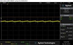
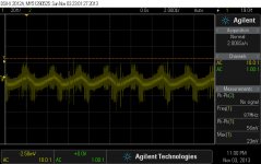
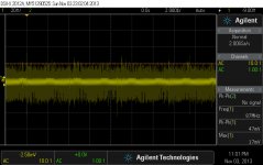
Here is the last edition of STX board (ASM), rev 1.00, with some measurements points and some descriptions of circuits.
I took snap shots of the switching PSUs on board for the analogue stage. The signals looks similar for +/- 12v rails. A/-A is right on the output diode of the PSUs. B/-B is after first ferrite bead on the filtering cell. C/-C is after last ferrite bead, last filtering cap (quite difficult to be seen on this picture).
The positive PSU deliver a tension level of 15v, and then is regulated by 7812 regulator. The negative tension is -12v right out of the PSU. No regulation here. The designed 7912 regulator is not populated. Positive/negative rails are rigorous equal. I do not know if this is just by chance on this board, or it is like this for all the production... Anyway it is a improvement comparing with the old edition STX boards.
Attachments
The measurements are made on untouched (original) PSUs on board. A/B/C are measurements points for positive rail, -A/-B/-C are for negative rail.
The card is powered through Molex connector for 5v/12v, and from PCIex for 3,3v.
I can not say for sure which of the Molex tensions are used for the +/- PSUs. This is not so important anyway. The 5v for DAC analogue stage is regulated from 12v Molex rail. The +/- 12v rails on board are also used for ADC stage of the card.
It looks to me that the 3,3v for ASM chip oscillator is taken from a own regulator (u21), and not directly from the 3,3v computer rail... In my opinion the oscillators on board it should be powered from a dedicated battery for better noise performances.
Last edited:
Thanks Coris...
Looks as if my 1.02 also had a switching PSU on board as well.
If one was to inject -12V regulated at u34 (?), the unregulated -12V first has to be removed from the design...do you see a way of doing this?
I think if you remove the molex power and add external 12V to the 7812, then the -12V would also get power...?
Sent from my iPhone...
- Home
- Source & Line
- PC Based
- Xonar ST/STX mods...