What do you think about this PCB. (It's the first PCB I've designed so go easy on me ") )
)
http://kotiweb.kotiportti.fi/audiovideo/DIY/kello/piirilevy.jpg
)http://kotiweb.kotiportti.fi/audiovideo/DIY/kello/piirilevy.jpg
Hi Diar,
The LT1763 is WAY better than the simple follower!
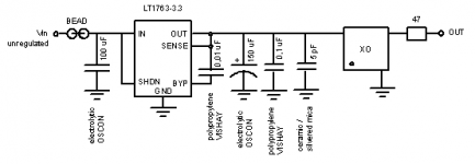
Omit the ferrite bead between the regulator and the XO, you want a low output impedance at all frequencies won't you?
Place the bead at the INPUT of the regulator!
Maintain a separate “LOCAL GROUND” remote from the “GROUND PLANE” to ensure a quiet ground near the LDO.

The LT1763 is WAY better than the simple follower!
Omit the ferrite bead between the regulator and the XO, you want a low output impedance at all frequencies won't you?
Place the bead at the INPUT of the regulator!
Maintain a separate “LOCAL GROUND” remote from the “GROUND PLANE” to ensure a quiet ground near the LDO.
 Oh dear..
Let's see if I understand.
I should change everything (except the 47 ohm resistor) to this:
]
An externally hosted image should be here but it was not working when we last tested it.
[http://www.linear.com/prod/datasheet.html?datasheet=520
and put the bead in front of the LT1763. This makes sense
.I really don't have a clue what you ment by the separate ground planes. I've seen this ground plane issue mentioned a thousand times but I just can't figure out what exactly people mean by this...
LDO?
Thanks for your help

EDIT: These seem to be rare. I couldn't find them at RS or Farnell.
Hi DIAR, I was meaning that the input and output cap are connected directly to the groundpin of the regulator rather than to the large groundplane surrounding the regulator. This in an attempt to make the loop as small as possible. The groundpin as then connected to the general groundplane by a short trace.DIAR said:
I really don't have a clue what you ment by the separate ground planes. I've seen this ground plane issue mentioned a thousand times but I just can't figure out what exactly people mean by this...
LDO?
Thanks for your help
LDO = Low-Drop-Out regulator.

How about this configuration?
Have I put too many caps in it? How about the brands? Are more expensive caps worth buying in this application?
Do I need a resistor in input? What's the function of the input resistor (10 ohms) in Tentlabs regulator configuration?
I found a few places in Finland that sell the LT1763 regulator. Hopefully they sell their products for private customers also.
EDIT: I changed the schema a bit. 3.3 uF to 100 uF.
Attachments

(ESR=Equivalent Series Resistance, I had never even heard of such thing )
According to the data sheet, ESR shold be less than 3 ohms.
The LT1763 regulators are designed to be stable with a
wide range of output capacitors. The ESR of the output
capacitor affects stability, most notably with small capacitors.
A minimum output capacitor of 3.3uF with an ESR of
3ohms or less is recommended to prevent oscillations.
ESR of OSCON caps is 30 mohms.
ESR of Vishay polypropylene caps is not told in data sheet
http://www.vishay.com/docs/26017/mkp1837.pdf
I guess the ESR is much much lower than needed so I don't think that should be a problem.
)According to the data sheet, ESR shold be less than 3 ohms.
The LT1763 regulators are designed to be stable with a
wide range of output capacitors. The ESR of the output
capacitor affects stability, most notably with small capacitors.
A minimum output capacitor of 3.3uF with an ESR of
3ohms or less is recommended to prevent oscillations.
ESR of OSCON caps is 30 mohms.
ESR of Vishay polypropylene caps is not told in data sheet
http://www.vishay.com/docs/26017/mkp1837.pdf
I guess the ESR is much much lower than needed so I don't think that should be a problem.

DIAR said:I guess the ESR is much much lower than needed so I don't think that should be a problem. [/B]
Hi
Lower ESR gives less damping of the LC network, so it could be a problem.
regards
Guido Tent said:
Hi
Lower ESR gives less damping of the LC network, so it could be a problem.
regards
Yes of course. Otherwise this would have been too simple
I will build both regulators LT1763 and the one that Guido recommend (I allready have the components).
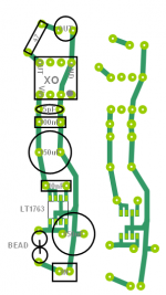
I made some changes to the PCB. I'm not sure if I understood this groundplane issue correctly so feel free to critisize.
Attachments
DIAR said:I designed a PCB for LT1765 regulator. It is a surface mount chip which I is to be connected to backside of the pcb.
Should I remove some caps. I feel I should, but which one?
http://www.tentlabs.com/Info/Articles/Supply_decoupling.pdf
enjoy
DIAR said:I designed a PCB for LT1765 regulator. It is a surface mount chip which I is to be connected to backside of the pcb.
Should I remove some caps. I feel I should, but which one?
I guess you mean the LT1763?
Widen the ground trace till it covers all unused space on the board. It is called groundfill. Remember the ground should have a low impedance as possible.
I don' t see much use for the pF cap as the XO has an 0.01µF SMD cap "under the hood".
Elso Kwak said:
I guess you mean the LT1763?
Widen the ground trace till it covers all unused space on the board. It is called groundfill. Remember the ground should have a low impedance as possible.
I don' t see much use for the pF cap as the XO has an 0.01µF SMD cap "under the hood".
Elso, others,
Reducing RF impedance only can be established by reducing the loop area of accompanying currents.
A ground fill is not needed to achieve that.
Ground fill works nice up to a few kHz, above that Maxwell should be respected......
regards
Too late
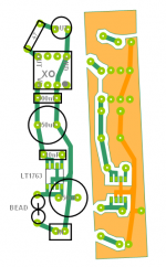
I added a larger groundplane but according to Guido I should remove it and stick with the original plan and have only thin traces for ground.
Thanks for the article. I've got a lot of learning to do today.
EDIT: I have previously attached some PCB plans for Tentlabs regulator configuration. The regulator should not be LM317 as written. It should be LM1708!
Attachments
[EDIT: I changed the schema a bit. 3.3 uF to 100 uF. [/B][/QUOTE]
-----------------------------------------------------------------------------------
Good idea. In practice, you want to swamp the harmonics/nooise spikes produced as a result of coupling to the XO. Forget about theory and look at the result on a wide band scope. I sometimes use 680u/6V OSCON. The LT1763 is better than most, from memory but has the higher inherent noise as per spec.
I also found it was necessary to have a very large ground plane to sreen out 50 Hz with the 1763. Just mount in on a grounded piece of circuit board.
DIAR said:Too late
I added a larger groundplane but according to Guido I should remove it and stick with the original plan and have only thin traces for ground.
Thanks for the article. I've got a lot of learning to do today.
EDIT: I have previously attached some PCB plans for Tentlabs regulator configuration. The regulator should not be LM317 as written. It should be LM1708!
Hi
You shouldn't remove it, I only wrote it doesn't help........
enjoy

- Status
- This old topic is closed. If you want to reopen this topic, contact a moderator using the "Report Post" button.
- Home
- Source & Line
- Digital Source
- XO powersupply PCB board diagram