The 2nd photo on page 3 of the 6Moons review 6moons audioreviews: Pass Labs XA30.8 shows 2 devices next to the ribbon cable connectors which I strongly believe are thermistors. Does anyone have an idea about where to purchase spring-loaded thermistors, or something similar that can go on the backside of an output board and make reliable thermal contact with the heatsink? Alternatively, how might one fabricate such a thing ordinary thermistors?
Add threaded hole above its position and you can use a dipped screw to shove it against the heat sink. That or thermal adhesive. Apparently regulated CLC psu. I guess the mono chassis and dual chasis version need a certain amount of heatsink just for the regulator
No, the thermistors help control the output bias current vs. temperature and connect to the bias circuit on the FE board.
The pics show an impressive amp.The 2nd photo on page 3 of the 6Moons review 6moons audioreviews: Pass Labs XA30.8 shows 2 devices next to the ribbon cable connectors which I strongly believe are thermistors. Does anyone have an idea about where to purchase spring-loaded thermistors, or something similar that can go on the backside of an output board and make reliable thermal contact with the heatsink? Alternatively, how might one fabricate such a thing ordinary thermistors?

though , our dear Srajan (me thinking of including him as external agent for OPLDF) had few mishaps ...... this for instance :
Here we get a glimpse of the 12 power supply caps per side, a small Tamura transformer or choke from Temecula/CA, two additional caps hanging sloth-like off the top board and assorted heat-sinked regulators.
why I didn't saw that article ...... or I'm not rememberint that I did ?
however , I wouldn't loose my sleep about last ounce of CCS performance in OS
My original question was whether there was any reason not to use a common-source CCS, which totally eliminates the bootstrap capacitor and has a lower parts count.
Hello lhquam. Maybe the schematic [and operation] of diyF5 helps your decision. Its output stage Mosfets at idle are thermally stable complementary CCSs.My original question was whether there was any reason not to use a common-source CCS, which totally eliminates the bootstrap capacitor and has a lower parts count.
Hello lhquam. Maybe the schematic [and operation] of diyF5 helps your decision. Its output stage Mosfets at idle are thermally stable complementary CCSs.
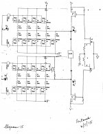
Hello lhquam. I thought more about about what I wrote above, and came up with the two attached schematics; which [imho] conform quite well with the knowledge in this thread. The left side of the left image shows:
1. Your artwork from a past post; which depicts a pair of complementary symmetry push-pull power outputs that are driven by balanced input signals Vi and Vi'
2. The upper PP power output stage has an extra P Mosfet [Q4]. I added an extra N Mosfet to match it in the lower PP power output stage.
3. The right part of this left image shows a diyF5-like power amp [just one] interfacing with both PP power output stages on its left.
4. The power output P Mosfet of diyF5 is the CCS for Q4; meaning that both are an SE amp.
5. The power output N Mosfet of diyF5 is the CCS for the extra N Mosfet in the lower left PP output stage. Both N Mosfets make another SE amp which is complementary to the above one.
6. The FE of diyF5 is idle, and provides the needed idle currents of its output Mosfets.
7. The load is connected between the power output ports at Vo and Vo'.
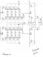
The right image has the same basic schematics shown in the left image with the following additions which may be valuable.
1. The FE of diyF5 has a switch. In position 1, it grounds the joint input of the JFETS. The result is a complementary dual CCSs from its power output stage as described above.
2. In position 2, a signal [Vi"] is presented to the input of diyF5 so as to modulate its power output current sources.
3. Negative feedback via the 2 resistors [Rf] is implemented so as to net like that in diyF5. May help lower the ouput impedance of the overall amp as you had wished in an earlier post.
Best regards
Attachments
Hello lhquam. I thought more about about what I wrote above, and came up with the two attached schematics; which [imho] conform quite well with the knowledge in this thread.
...
Best regards
Those are unusual circuits. Have you simulated them? I suggest you get up to speed on using LTSpice if you haven't already.
There is an error on those schematics in that the front end appears to
be driving the outputs directly, unless I am mistaken.
But to address the more familiar point, there's a dozen ways to skew the
gain asymmetrically so as to create 2nd harmonic, and this would only be
one of them. I have seen designers who have done it accidentally through
poor pcb layout.
My observation is that you will want to try the different ways and see which
of them floats your boat. This is often a subjective thing, and you will want
to be the judge, not me.
Oh, and those are thermistors in the photo. I don't need to actually glue
them to the sink - the thermal time constant is so large that there's no
problem with tracking.
There is an error on those schematics in that the front end appears to
be driving the outputs directly, unless I am mistaken.
...
If you are referring to my schematics, the sine wave voltage source is a simulation of the other push-pull output FETs on the output board. What I was trying to show was how the CCS current behaves as a function of the output rail voltage.
OTOH, perhaps I am completely missing the "secrets" of the XA.8 output board design, thinking that it merely replaces one FET with a CCS on opposite rails of the +phase and -phase.
Those are unusual circuits. Have you simulated them? I suggest you get up to speed on using LTSpice if you haven't already.
Hello lhquam.
Unusual circuits? Why so? The schematics [like the left image in my past post] emanate from your contributions to this thread. I depict them as compound amplifiers of a diyF4 amplifier [PP output stage; your words] and a diyF5 [my words] operating in CCS mode. This diyF5 may also operate like a normal power amplifier to give a modulated current source mode. One simply needs to manage the levels of Vi =Vi" which is/are different in magnitude from Vi" input to diyF5..
B]Have I simulated them[/B]? No. What for? DiyF4 and diyF5 have been simulated [most probably by you and others], are well established, reputable amplifiers which are currently alive, well and healthy.
Best regards,
Hello lhquam.
...
B]Have I simulated them[/B]? No. What for? DiyF4 and diyF5 have been simulated [most probably by you and others], are well established, reputable amplifiers which are currently alive, well and healthy.
Best regards,
Any time you make modifications or compositions of circuits the results can be rather different from your expectations. You need to verify the behavior either mathematically, thru simulation, or actual construction.
There is an error on those schematics in that the front end appears to
be driving the outputs directly, unless I am mistaken.
But to address the more familiar point, there's a dozen ways to skew the
gain asymmetrically so as to create 2nd harmonic, and this would only be
one of them. I have seen designers who have done it accidentally through
poor pcb layout.
My observation is that you will want to try the different ways and see which
of them floats your boat. This is often a subjective thing, and you will want
to be the judge, not me.
Oh, and those are thermistors in the photo. I don't need to actually glue
them to the sink - the thermal time constant is so large that there's no
problem with tracking.
Hello Mr. Pass. Please clarify the error in my schematics.
Best regards,
....
My observation is that you will want to try the different ways and see which
of them floats your boat. This is often a subjective thing, and you will want
to be the judge, not me.
.....
Nelson,
is that the reason why you don't use Aleph current sources instead of constant current sources in your XA.8 amps? I am wondering, because to me, in theory and simulation they seem to be very appropriate in these amplifiers.
"main" thing in Aleph CCS is that thingie is modulated ; here is no need for CCS to be modulated , so no possibility to establish Aleph CCS
so , taking aside wittiness needed to make a difference , difference between Aleph CCS and so called Widlar Current Source*** is no more than few strategically placed resistors and one capacitor ........... establishing pole where CCS programing voltage and modulating signal are combined to govern mighty mosfet
edit: *** #3320439
Last edited:

- Status
- This old topic is closed. If you want to reopen this topic, contact a moderator using the "Report Post" button.
- Home
- Amplifiers
- Pass Labs
- XA.8 single-ended current sources