Hello all,
Newbie posting!
Not only am I newbie here at diyAudio, I am green as grass when it comes to DIY in general. So what is a newbie to do? Jump right in of course!
I just purchased some boards from peter last evening and I am excited! I will be leaning on some of you for help in the coming weeks/months, but I will research and try to ask good questions. Still, there will be those moments....
Btw, does someone have a set of matched fet's I could buy for my F4 clone project?
Bsuhy--I live 50 miles down 37 and work in Indy, but I can't email you until I've finished my mod time..............................
Cheers to all and have a safe and Happy New Year!
Gary
gbeard said:does someone have a set of matched fet's I could buy for my F4 clone project?
here:
http://www.diyaudio.com/forums/showthread.php?s=&threadid=110654&highlight=
or
http://www.diyaudio.com/forums/showthread.php?s=&threadid=81051&highlight=
Matched mosfets
Just to give you another option ...
I purchased mine from Jack (member of this forum, jackinnj) at The Company Store. I have no vested interest in his business, but he has always been very responsive and reliable. I believe his prices are substantially less than the previous two options listed. (Edit: there appears to be some confusion in the price quote I received from landoctor and the price quoted in the links above for matched fets ... so my comment on prices should be verified for yourself) I also purchased input jfets for my F-4 from his site. Here's the link:
http://tech-diy.com/hexfets.htm
Hope that helps.
Ryan
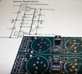
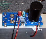
There was a question how to use the PS boards with adjustable regulators for low current applications.
Attached picture shows it for LM317 (top) and LM337 (bottom), the orientation and placement of TO-220 regulators is critical as the supply boards work with symetrical voltages.
The other parts values are according to schematic in a picture:
R1/R3 = 120R
R2/R4: adjustable 2K, can be later replaced with a fixed value
C1-C4 = 0.1uF (optional, any other small value should work fine too))
C5/C6 = 10uF
The diodes placement was discussed here: http://www.diyaudio.com/forums/showthread.php?postid=1237672#post1237672 ; choose any suitable values for large caps. Although grounds are shown as common in a schematic (courtesy of National Semi), they are kept separately on my boards.
That arrangement is also good for LT1086/LT1033.
The other two spots are reserved for LM78xx/LM79xx
Attachments
- Status
- This old topic is closed. If you want to reopen this topic, contact a moderator using the "Report Post" button.