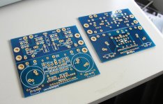
Now I have shortened my layout down to 250x100mm. Distance between mounting holes on output transistors have decreased from 5 cm to 4 cm.
I have uploaded the current layout so you can see how it looks.
The silk screen has not been cleaned up, but I'll do that before the layout goes to print. Mounting holes, drill sizes and absolute placement of the two channels also needs to be sorted.
I'm open to suggestions and tweaks.
I have uploaded the current layout so you can see how it looks.
The silk screen has not been cleaned up, but I'll do that before the layout goes to print. Mounting holes, drill sizes and absolute placement of the two channels also needs to be sorted.
I'm open to suggestions and tweaks.
Attachments
Banned
Joined 2002
")
Banned
Joined 2002
cviller said:And then you have one "set".
Does a set include power supply?
Banned
Joined 2002
shallbehealed said:
Does a set include power supply?
I could include psu boards i'm currently working with briangt to make them a little smaller.
The design is based on my other board, A30, and has exactly same size and output devices spacing. So if if anyone built A30 with those PCBs, they can simply swap boards and use F4 in a same chassis now (adjusting transformer voltage may be required)
http://www.diyaudio.com/forums/showthread.php?postid=610637#post610637
http://www.diyaudio.com/forums/showthread.php?postid=613190#post613190
http://www.diyaudio.com/forums/showthread.php?postid=610637#post610637
http://www.diyaudio.com/forums/showthread.php?postid=613190#post613190
They will be beautiful blue, like in attachment. As to Dales, they will only fit in vertical position. I may consider going with full size resistors, but somehow those miniature resistors seem to fit here very well. And I was designing the board with a thought of using Caddocks or Vishays, that's why such small footprint.
Attachments
Banned
Joined 2002
- Status
- This old topic is closed. If you want to reopen this topic, contact a moderator using the "Report Post" button.