Hi jonni ! 🙂
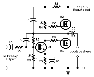
This project was a sort of challenge: designing an audio amplifier capable of delivering a decent output power with a minimum parts count, without sacrificing quality.
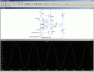
Mini-MosFet Audio Amplifier - RED - Page123
This project was a sort of challenge: designing an audio amplifier capable of delivering a decent output power with a minimum parts count, without sacrificing quality.
Mini-MosFet Audio Amplifier - RED - Page123
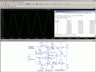
I am not sure this circuit will work as intended: the auto-bias circuit relies on the control transistor switching from diode to transistor, and for that to occur, there has to be minimal interference from extraneous components.🙂
The transistor T3 in active mode and never goes into saturation.
I think the resistors will constrain the operation to a very narrow range of supply voltages, and the capacitor will act as a peak detector, thus dynamically changing the bias current with the audio program.
Something like Visch's circuit's flaw.
Hi jonni ! 🙂
This project was a sort of challenge: designing an audio amplifier capable of delivering a decent output power with a minimum parts count, without sacrificing quality.
Mini-MosFet Audio Amplifier - RED - Page123
Rail-to-rail version:
Attachments
Last edited:

it reminded me of the buffer circuit buf634
BUF634T Datasheet pdf - 250mA High-Speed Buffer - Texas Instruments
regards
BUF634T Datasheet pdf - 250mA High-Speed Buffer - Texas Instruments
regards
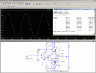
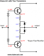
The auto-bias scheme scheme can be applied to more "evolved" designs, like the one proposed by John.
In this minimalist forms, it suffers from some minor deficiencies: although it does not suffer conventional crossover distortion, there are some "crossing artifacts" caused by the time taken by Q3 to get out of deep saturation.
Adding an antisaturation diode improves matters.
Using one or two diodes to reduce the swing seen by Q3's collector helps iron out the last residues.
Adding the diodes somewhat reduces the bullet-proof thermal ruggedness of the circuit, but even with two diodes, the voltage across the bases is bound to VD2+VD3-VD1, which means there is still ~1/2Vbe safety margin, quite sufficient for a "normal" environment.
Further sophistication is possible, to improve some parameters, like adding a second transistor to make the circuit symetrical, add B-E resistors, a holding capacitor, etc, but the circuit then loses some of its appealing simplicity.
Hello
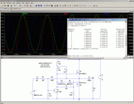
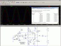
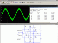
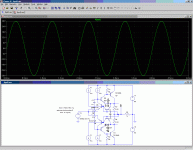
What did you do in your Ltspice simulation so it can show "crossing artifacts" ?
Thank
Bye
Gaetan
Simply zoom with the mouse on the crossing region....What did you do in your Ltspice simulation so it can show "crossing artifacts" ?
I zoom in on where the currents cross to get the time, then click on the voltage.
Otherwise a small glitch is sometimes difficult to spot where to zoom in on...
Otherwise a small glitch is sometimes difficult to spot where to zoom in on...

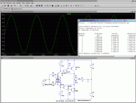
I am afraid that one wouldn't work very well in reality: there is a good level of compensation regarding the V-I characteristic of the two transistors, but the compensating transistor will also amplify any temperature differential between the sense and output transistor: unless you use a Thermal trak device or similar, the output stage will be dangerously prone to thermal runaway.auto-bias version
I have used successfully a comparable scheme, but with emitter degeneration resistors. And it was symmetrical. I 'll try to dig up the thing.
Anyway, even in this form, it is moderately valuable; let's say it's interesting, but of no real practical value.
If you want the real, effective version, here is the way to go:
http://www.diyaudio.com/forums/solid-state/202684-class-i-siblings.html
Of course, it is not that simple anymore, the loop gain requires some attention, and there are a number of matching issues.
But as the saying goes, "there are no free lunches ...etc
If you want the real, effective version, here is the way to go
I will try as simple proposals to express their thoughts to an automatic translator was able to bring even be a little sense.
Interesting to whether there was useful for this discussion is topikstarter?
Hello Elve!
Looked amplifier circuit class i.
Created soundly!
However, the scheme of your Сirklotron liked me more.
Especially successful in it are power Schottky diodes!
I understand how it works, but something I would have changed.
Best wishes!
Last edited:
Darn my internet connection is really slow, but this is very interesting thread. I'm an E.E. and have to admit, that I'm impressed with the answers and circuits submitted.
I would think that Radio Shack would have something with a circuit board and kit parts etc.
If I get a chance, I'm tempted to go there right now, I'll see what that have. Of course you can also look online( I would but my line here at Starbucks" is really slow).
Very interesting.
btw the OP didn't mention what his/her input signal would be? Microphone, Earphone out put on Laptop ?? .. I would like to build a little amp for Microphone's.
... very interesting article.
More circuit kits here. ... this is for a guitar NightFire Electronic Kits : (#1127) Mini Guitar Amplifier Kit - $8.99
I had somewhat lost sight of my promise to post my (working) version.I will try as simple proposals to express their thoughts to an automatic translator was able to bring even be a little sense.
Interesting to whether there was useful for this discussion is topikstarter?
Here is the circuit in question, plus one or two variations on the same theme.
....And a selection of some "funny" circuits. I kept the best ones to myself though (for the moment) 😀
Attachments
We all continue to move away from the original topic. But apparently it's not very worried about Coconuts 500.
From the presented diagrams, I liked the most bcliq6.gif, which is attempting to get the mode of the output stage in a dynamic class A.
Theoretically, it looks nice, but in practice it does not work.
The larger effect is obtained from the powerful Schottky diodes, which you have in the scheme Cirklophone.
The same principle is shown in the attachment.
Attachments
Last edited:
Not really; anyway, I am not too sure about it (dynamic class A?)We all continue to move away from the original topic. But apparently it's not very worried about Coconuts 500.
From the presented diagrams, I liked the most bcliq6.gif, which is attempting to get the mode of the output stage in a dynamic class A.
I can assure you it does work (also depends on what you qualify as "working"): I have built actual prototypes.Theoretically, it looks nice, but in practice it does not work.
The stability issues are not straightforward, and I did blow a number of OP pairs trying to tackle it.
That is completely different: what you show is something like class AC, by J. Broskie. Quite valuable, but different.The larger effect is obtained from the powerful Schottky diodes, which you have in the scheme Cirklophone.
The same principle is shown in the attachment.
In the Circlophone, the only reason for including the diodes is to reconcile a good power efficiency (nearly rail to rail output) with a good quiescent current control without matched or thermally coupled (or worse, monolithic) sensing transistors.
You can build a Circlophone with ordinary fast silicon diodes, or even no diodes at all.: it will work in all cases, but the efficiency will be dismal.
The diodes have no role whatsoever in shaping the transfer function of the amplifier, they are mere expedients.
In the class AC, their crossing characteristic does influence the open-loop transfer function of the amplifier. That's quite different.
I would like to build a little amp for Microphone's.
little amp for Microphone's with auto-gain 🙂
Attachments
Last edited:
- Status
- Not open for further replies.
- Home
- Amplifiers
- Solid State
- Would like to build super simple mini transistor amplifier