Hi Guys
For the TO-92, the leads are spaced by 100mil, the copperless space between the pads is 47.5mils.
When inserting the BJT, you angle the device slightly and insert the lead at one end, then the middle then the other end. The leads flex easily and you would never push the body all the way down to the board, so the leads are splayed without effort and the part is very secure.
For TO-126s, their leads are already spaced at 100mils so generally I leave them at that. If I want to position them close to a larger device where it would be convenient to bring a fat trace through the TO-126 foot print, I have a "wide" version of this footprint where the leads are slightly splayed. Same for TO-220.
You also have to remember that the bodies of these parts can be thick. In most cases the air above an adjacent resistor or other low-profile part can take up that slack, but you should accommodate it with at least one variant of the library package for the device.
For example, I have fourteen packages that an NPN, PNP, NMOS or PMOS can be, covering small packages like the Japanese SST (like a TO-92 with the back half cut off), to TO-92s, TO-126, TO-220, TO-247 (16mm wide), TO-264 (20mm wide), with normal spacing and with staggered high-voltage spacing. I build circuits that have to handle 1kV, so the standard TO-220 footprint doesn't work for me especially with fat pads.
In the "slim" package variations where I do want to have a tight spacing, I add E,B,C indications on the top silk screen so I orient the part correctly.
Have fun
Kevin O'Connor
Last edited:
I always have to translate to metric, so on the fly it's not so easy for me to perceive the actual sizes if not in metric units. Now that I looked at this closer, I see what you mean, the TO92s have lead spacing at 50mils, but the TO126/220s double that. So it's not really that much of a stretch to spread the leads on those small signals, it can be done without much trouble.
I am taking good note of your remarks.
Would you mind sharing some of your eagle parts library? Yours must be done right, which would certainly be better than the ones I am making.
I am taking good note of your remarks.
For TO-126s, their leads are already spaced at 100mils so generally I leave them at that. If I want to position them close to a larger device where it would be convenient to bring a fat trace through the TO-126 foot print, I have a "wide" version of this footprint where the leads are slightly splayed. Same for TO-220.
In the "slim" package variations where I do want to have a tight spacing, I add E,B,C indications on the top silk screen so I orient the part correctly.
Would you mind sharing some of your eagle parts library? Yours must be done right, which would certainly be better than the ones I am making.
I've been looking at various options possible to prevent overloads from over driving signals.
I am looking at multiplying the protections and eliminate the vi limiters entirely.
Even if the amp has been made to keep a "good" behavior when clipping, I want to insert a kind of limiter or compressor ahead of the amp, to keep its clipping to a minimum and absolutely prevent any hard clipping. Only slight temporary clipping must be allowed, which at small levels would hopefully not do any harm to speakers.
Among the options that I've been looking at, are the ones used by carver, crown, crest, etc...
And also this one:
http://rupertneve.com/products/portico-5043/
This is a separate device that is inserted before the amp, and it has its own cost, plus the extra cabling to hook it up of course.
This would be a little more than I am looking for and as a diyer, I'd rather build my own and build it in the amp itself. So I'll be looking at all the options that I can find and hopefully come up with something that I can simulate and then build.
I like your amp! But, as mentioned before, I would not use that top cover with that "much" ventilation. I know ventilation is good for the amp, but that much is bad
How bad? Well it is not only that some kind of metal can go inside by mistake, But also water or any liquid too...ooh and do not forget that "dust" is a bad thing for electronics too and with that much ventilation it will be easy to accumulate dust inside. if you want to see the guts inside your amp....well take a few pictures
Do not take it wrong, it is a recommendation only...at the end it is your amp and you can do anything you want to it
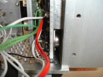
I encountered the same problem by "dust", I use a stainless mesh to improve it (left side of the attached photographs), at least it becomes easier for cleaning.
John
Attachments
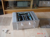
I encountered the same problem by "dust", I use a stainless mesh to improve it (left side of the attached photographs), at least it becomes easier for cleaning.
Looks very nice. The thickness of the case must add to the performance of the heat sinking.
My design can be made with a choice of top case easily, so depending on who makes it, the appropriate case design can be chosen.
From my own use, there is no way in hell any liquid could even come close to it, plus I only plan to use it in a rack, so the only real issue is dust, and I can live with that. I quick look inside can reveal any dust invasion, and it's time to open it and use the vacuum... It's a matter of preference. I prefer maximum ventilation, but others have other views. It's no problem.
I haven't had any time for hobbying in many months now, so the project is stalled for the moment, but I'll get back into it later and I will draw one more alternate case design to satisfy those who are overly paranoid about dust and debris.
There are several other ongoing projects that I was working on and I will get back to this as soon as I can spare the time.
I use vacuum to clean most of the stuff in my house , they include desktop and notebook PC, stereo components, TV, furniture, floor....
My implementation for Leach SuperAmp is 20 years old -- drill was the only tool for me to make the chassis, the whole structure was too complicate for assembly -- too many screws, too much wiring and thermal paste!
Your implementation is really awesome, I love and enjoy it!
I can tell you are an expert in modern tools (CAD software ...), looking forward your every publish on diyAudio.
John
My implementation for Leach SuperAmp is 20 years old -- drill was the only tool for me to make the chassis, the whole structure was too complicate for assembly -- too many screws, too much wiring and thermal paste!
Still a very nice job. Good looking thing.
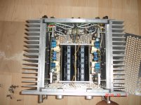
I have one question though. Maybe the photos are not revealing enough details about this. How are the TO3s heat linked to the heatsinks? They look like they are on some plate on their own and only studs linking those to the heatsinks...
Your implementation is really awesome, I love and enjoy it!
Glad you like it. I will get back to this soon and I will provide all the details, drawings, etc...
I can tell you are an expert in modern tools (CAD software ...), looking forward your every publish on diyAudio.
Well, I wouldn't call myself an expert, not really, but I can handle my own with that stuff. I use as many of the tools as possible to do the design as thorough as possible.
Having CAD files of everything really helps making this much more duplicatable. I am in relations with various manufacturers, many in china, and I sometimes have shipments coming from them, so I will eventually have my hobby parts made by them as well and have them shipped with the other things.
There has been some serious reflection done about this amp and I will be making some alterations to it. For example I plan to use solid state relays only, for the output muting, and on each rail. Other things in mind too... But no time for hobbying for now, unfortunately. I'll get back into this later.
spookydd:
what CAD are you using for the 3D? that's pretty good looking.
mlloyd1
what CAD are you using for the 3D? that's pretty good looking.
mlloyd1
I had planned for 2 smaller heatsinks on the pcb, including one for the 2 rectifier bridges at the psu end of the board. That one is an SK597. All Fischer heatsinks ...
what CAD are you using for the 3D? that's pretty good looking.
It depends on what I can get access to at a certain time. Could be solidedge, spaceclaim, or solidworks, but I am more adept at solidworks, so I have been solely using it for that design. No need to mix formats to make things too difficult. So I will keep using solidworks for this project.
I always try to do this with the most precision possible, and I use data from datasheets or if possible from actual parts to draw them properly.
I don't have the Fischer heatsinks on hand though, but they provide good enough data about them, so the drawings should be accurate.
The renderings are mostly done with photoview360 in solidworks, but sometimes I also use sketchup.
I hate windows, so I try staying away from it, but I have no choice but to use someone's peecee so I can use solidworks or an other cad program. I have not yet seen any decent program for mac. That is one that is affordable. There is Siemens NX, but that's hugely expensive.
I have one question though. Maybe the photos are not revealing enough details about this. How are the TO3s heat linked to the heatsinks? They look like they are on some plate on their own and only studs linking those to the heatsinks...
[/QUOTE]
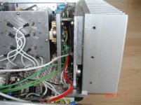
Please refer the attached photographs, there are total 3 thermal junctions by my build:
junction1: TO3 to 4.5mm Al plate (actual is TO3 to mica sheet + mica sheet to 4.5mm Al)
Junction2: 4.5mm Al plate to 10mm Al plate
junction3: 10mm Al plate to main heat sinker
This is not a good structure for thermal conductor even my build is sufficient for my daily use.
The wiring from 16 TO3s (my build is 8 TO3s x 2-ch) to main PCB can really makes people exhausting by this structure!
It looks to reduce the thermal junction (resistance) between output power Tr. to main heat sink is good approach and the modern plastic package power Tr. seems better solution for this approach.
John
[/QUOTE]
Please refer the attached photographs, there are total 3 thermal junctions by my build:
junction1: TO3 to 4.5mm Al plate (actual is TO3 to mica sheet + mica sheet to 4.5mm Al)
Junction2: 4.5mm Al plate to 10mm Al plate
junction3: 10mm Al plate to main heat sinker
This is not a good structure for thermal conductor even my build is sufficient for my daily use.
The wiring from 16 TO3s (my build is 8 TO3s x 2-ch) to main PCB can really makes people exhausting by this structure!
It looks to reduce the thermal junction (resistance) between output power Tr. to main heat sink is good approach and the modern plastic package power Tr. seems better solution for this approach.
John
Attachments
Hi, if you can get 15mm aluminum blocks and have it machined to a thickness of about 6mm where the TO-3's are to be mounted, that will lessen the thermal junctions...
Yes, it could be one of the option for my future build.
Tks,
John
Junction2: 4.5mm Al plate to 10mm Al plate
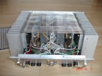
I think that is the one that puzzles me.
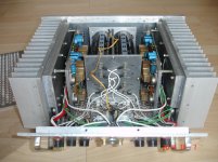
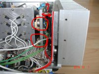
I circled the TO3s that I am wondering about on one of your photos (attached here).
Those are on a plate, that may be one of those 4.5mm plates you mentioned.
I am wondering how the thermal link is made from those to the main heatsink via that other large plate (marked with the vertical bar).
I can see other TO3s on that thick plate on the right, but what about those on the left? I only see them sharing that plate and only studs are holding that to the main heatsink.
Am I missing something?
Attachments
Always mount the electrolytic capacitors, vertically.
Gajanan Phadte
Understood, it was a compromise layout to fit overall chassis dimensions.
So far it works well over 20 years.
John
I think that is the one that puzzles me.
I circled the TO3s that I am wondering about on one of your photos (attached here).
Those are on a plate, that may be one of those 4.5mm plates you mentioned.
I am wondering how the thermal link is made from those to the main heatsink via that other large plate (marked with the vertical bar).
I can see other TO3s on that thick plate on the right, but what about those on the left? I only see them sharing that plate and only studs are holding that to the main heatsink.
Am I missing something?
I use TO3 for driver, the circled TO3s on the small plate are the drivers. It according the initial design that M. Leach published in 1975.
The reversion layout in M. Leach current website use TO-220 for driver and locate on main PCB.
I think this may be the reason makes you confused.
There are 8 output TO3s located on the plate that you marked with red vertical bar, there is a 10mm thick plate between it and main heat sinker.
John
Understood, it was a compromise layout to fit overall chassis dimensions.
So far it works well over 20 years.
John
Now, rotate them 180 degrees.
Gajanan Phadte
- Status
- This old topic is closed. If you want to reopen this topic, contact a moderator using the "Report Post" button.
- Home
- Amplifiers
- Solid State
- Work In Progress... Leach Based Amplifier