how?
Hi,
my experience is that the wire coming out of the box as it is has some kinks which You can´t get perfectly straight by just pulling. My method was to fix one end of the wire and to use a drilling machine and pull for the other end. This way the wire became perfectly flat. I tested each wire by letting it roll down on a slightly tilted (10°) glass plate. This way even flat looking devices were sorted out when they didn´t pass the test. While it is a good and typical DIY-method (excellent results but takes too much working time") ) You can only use it for panels with just a few wires. If You want to use thinner wire it ends up in ridiculous time consumption.
) You can only use it for panels with just a few wires. If You want to use thinner wire it ends up in ridiculous time consumption.
I considered the method John.G proposed too, but I like my ESLs to be of an optically open style without cloth etc. so eggcrate wasn´t on my list. Too, with this method You still have something to do by cutting and soldering every wire.
Thats why I thought about a method of winding ´back and forth´ and not round and round´.
I think of a kind of jig with a row of pins at both ends to wind the wire on and to glue the stator frame on the wires.
The wire would come of off the box and would run through a device consisting of several roller dressers (?) with perpendicular (or at least some angular) orientation to each other. Together with the bending this device could supply for the needed and constant pull. When the wire is bent slightly and pulled in different directions every kink in it vanishes. The device could be made up of two or three rollers (ball bearings or just rods with smooth surfaces or those ceramic rings for fishing rods)...so nothing complicated big or heavy.
What do You think?
jauu
Calvin
Hi,
my experience is that the wire coming out of the box as it is has some kinks which You can´t get perfectly straight by just pulling. My method was to fix one end of the wire and to use a drilling machine and pull for the other end. This way the wire became perfectly flat. I tested each wire by letting it roll down on a slightly tilted (10°) glass plate. This way even flat looking devices were sorted out when they didn´t pass the test. While it is a good and typical DIY-method (excellent results but takes too much working time
) You can only use it for panels with just a few wires. If You want to use thinner wire it ends up in ridiculous time consumption.I considered the method John.G proposed too, but I like my ESLs to be of an optically open style without cloth etc. so eggcrate wasn´t on my list. Too, with this method You still have something to do by cutting and soldering every wire.
Thats why I thought about a method of winding ´back and forth´ and not round and round´.
I think of a kind of jig with a row of pins at both ends to wind the wire on and to glue the stator frame on the wires.
The wire would come of off the box and would run through a device consisting of several roller dressers (?) with perpendicular (or at least some angular) orientation to each other. Together with the bending this device could supply for the needed and constant pull. When the wire is bent slightly and pulled in different directions every kink in it vanishes. The device could be made up of two or three rollers (ball bearings or just rods with smooth surfaces or those ceramic rings for fishing rods)...so nothing complicated big or heavy.
What do You think?
jauu
Calvin
Attachments
how about this?
Calvin: not sure what gage wire you are using but it sounds much larger than what I use. I agree with you about the work necessary to solder together the stator wires and that is why I tell people to place the threaded rod at the narrow end of the stator panel so there will be less connections to make. One could take a half inch diametre threaded rod abd have a 90 degree section milled out of it across its length. Given 28-30 gage wire size this would then allow the stator wire to be simply looped around each thread as the wire serpentines back and forth between each end of the stator on it way across the stator panel. The threaded rod could also be set up so that it could be turned on its axis. When the stator is wound and the wires bonded to the stator panel the threaded rod could be rotated to allow the wires to slide off of the jig. These small (connected) loops could then be tucked down into the stator frame out of the way and no soldering would be required (though the panels do sound better if all the wires are connected).
This does not adress your issue however as you require much thicker wire to bridge the large gaps in between your support struts. What about small gage welding rods with a PVC shrink tube for insulation? Or the stator could be built up with uninsulated welding rod (TIG welding rod comes with a copper clad) then each rod could be solder connected and then after completion the stator could be electrostatically spray painted to insulate the wires. (powder coating would be too hot for the solder joints) You have probably thought about all this before so I hope that I am mentioning something or some method that you have not considered. The other tact you might also consider is that of the ols Quad. Perf plastic stators with the conductive coating on the outside with an over layer of insulation to make them safe to touch. Good luck and have fun. I enjoy reading your posts and your projects look great. Best regards Moray James.
Moray, thanks for the complements on my idea. I especially like your suggestion of placing the eggcrates for both stators right on the jig. This could save a lot of time. Too bad I won't get to this until late summer.
As an aside, here are some FEM results using FEMM to look at the field for a 20 wire/inch stator with stator-stator spacing of 3mm with 2kV across the gap. Ideally this would give a field of 670kV/m. The results show that there is only a small penalty to pay even given the greater than 50% open area.
Also note that you can eyeball-average the field and it does not vary much. FEMM is capable of determining the force on a charged membrane, but I'm already convinced by what I see that a 26AWG stator at 20 wires per inch is pretty good. I chose 26AWG because I have two spools of about 4000 feet each.
John
Attachments
very cool sims
John: not sure if you caught the idea but if yes forgive me and if not well once more. The idea was to actually make the egg crate stators the jig itself. By attaching them (the egg crate grids) back to back with the inside surfaces facing out and the threaded rods set into a wooden strip placed at each end you can wind directly onto the stators themselves with nothing but the rods at each end . A thin spacer inbetween and in the middle of the two stators will generate a small outward bow in the stators which will ensure a firm uniform contact between the wire and the grid.
I think that most thin diaphragm materials will end up better damped with somewhat less open area rather than more. I mentioned an open area of somewhere between 35-40 percent. Good luck this summer on your project. regards Moray James.
Here's a sketch based on some of the ideas I've read about in this thread. I've not built or tested this yet so if you see fundamental flaws I ought to address please let me know. I want to be able to adjust the wire tension without having to do it for every individual wire. If I use somewhat heavy wire, I'd also like not to have to rely on hand tensioning. I'm imagining electrically breaking the stator into one-inch wide strips and using one hook for each strip. There would be simple pins on the other end of the jig to match the hooks shown here.
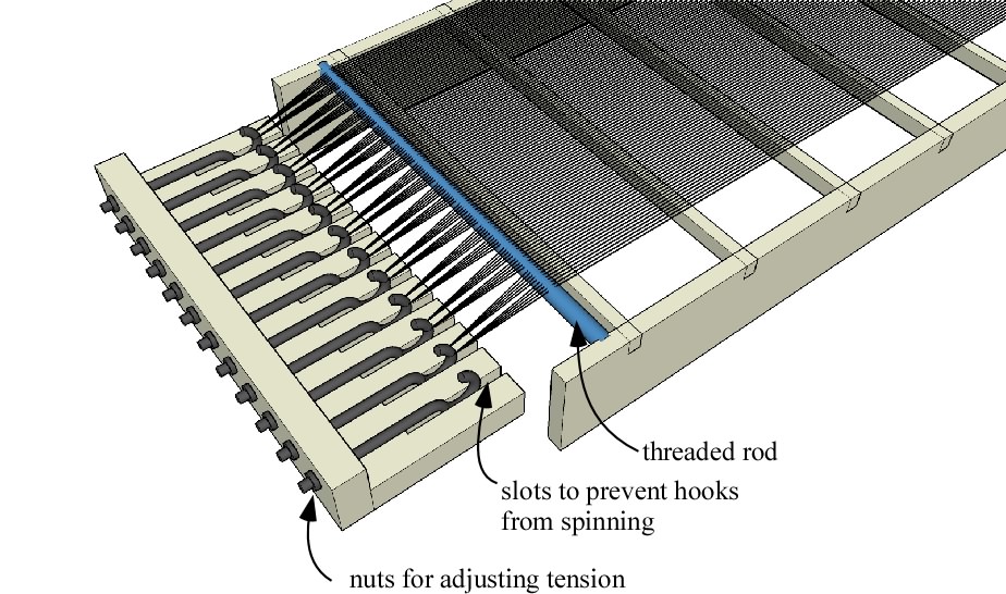
Obviously there are some construction details yet to be worked out but hopefully there's enough here so that the ideas are clear. Suggestions for improvements or refinements would be welcome.
Few
Obviously there are some construction details yet to be worked out but hopefully there's enough here so that the ideas are clear. Suggestions for improvements or refinements would be welcome.
Few
Nice concept and drawing, Few. How about raising the side boards and threaded rod up the thickness of an egg-crate louver so the louver could be slid between the wires and crossbars while you're stringing the wires. That would make glueing the wires down quite easy. That's assuming you're using egg-crate louvers as a base.
Lukas, have you figured out a glueing method? You told me about super glue in the The ESL Build Thread and it worked out very well. I imagine it would work on wire, too.
Lukas, have you figured out a glueing method? You told me about super glue in the The ESL Build Thread and it worked out very well. I imagine it would work on wire, too.
Looks great!
Few: I think that you will find that with small gage copper wire you can only generate so much tension but that it will be enough so long as your support structure is not too large (3/4 of an inch or less). Winding by hand will generate more than enough tension to distress your frame (tension multiplied by each wire). Remember too that you have to anchor the wires to the frame and hold them under tension. I think that it makes more sense to increase your wire support and use less tension as this will place less demand on any adhesive that you use to hold the wires in place (also makes for more points to bond at). Remember that most adhesives that you can use are really just very snugly encapsulating the wire to the frame so the strength factor is not really all that high. Hand winding very quickly becomes quite consistant. Variations in individual wire tension will only aid in spreading your resonant modes which is not a bad thing. If you take a look at the successful commercial designs you will see that the egg crat louvre idea has been used in some of the best (Acoustat and the Quad 63). Wether or not this meets with your asthetic ideal is of course another issue. Best regards Moray James.
Few: I think that you will find that with small gage copper wire you can only generate so much tension but that it will be enough so long as your support structure is not too large (3/4 of an inch or less). Winding by hand will generate more than enough tension to distress your frame (tension multiplied by each wire). Remember too that you have to anchor the wires to the frame and hold them under tension. I think that it makes more sense to increase your wire support and use less tension as this will place less demand on any adhesive that you use to hold the wires in place (also makes for more points to bond at). Remember that most adhesives that you can use are really just very snugly encapsulating the wire to the frame so the strength factor is not really all that high. Hand winding very quickly becomes quite consistant. Variations in individual wire tension will only aid in spreading your resonant modes which is not a bad thing. If you take a look at the successful commercial designs you will see that the egg crat louvre idea has been used in some of the best (Acoustat and the Quad 63). Wether or not this meets with your asthetic ideal is of course another issue. Best regards Moray James.
Hey Bill
Light louvre is available in two different base materials. The most common and the least expensive is Styrene and the less common and much more expensive is Acrylic. You get what you pay for. The Styrene is full of plastisisor which over time sweats out leaving the material brittle. Adhesives such as super glues may well bond to the new clean Styrene but the plastisisor will sweat out over time and literally float the glue bond. That is the reason that James Strickland of Acoustat chose to use Styrene disolved in solvent to encapsulate the stator wires in place. This solvent weld method is cheap deals with this issue and works well. Super glues are also very toxic and used in such a large scale as a project lke this by diy people without much or any safe air extraction equipment is to me unacceptable. They present serious heahth hazzards used in this way. I have worked with these adhesives under industrial conditions with chem lab fume extraction systems and still have suffered health issues. So be careful just because you can buy it at the grocery store does not make it safe. What ever base plastic you choose to use you will greatly increase your sucess with bonding if you surface sand it first to remove any mould release agents and to increase your surface tension. Remember that unless you are solvent welding adhesives work by getting into surface irregularities and wedging themselves there like a rock climber looking for a crevas to get his fingers into. So the more surface tension the better, same reason why you scuff paint surfaces between coats. By the way Bill your work is excellent thank you for sharring with everyone on the forum. Best regards Moray James.
Light louvre is available in two different base materials. The most common and the least expensive is Styrene and the less common and much more expensive is Acrylic. You get what you pay for. The Styrene is full of plastisisor which over time sweats out leaving the material brittle. Adhesives such as super glues may well bond to the new clean Styrene but the plastisisor will sweat out over time and literally float the glue bond. That is the reason that James Strickland of Acoustat chose to use Styrene disolved in solvent to encapsulate the stator wires in place. This solvent weld method is cheap deals with this issue and works well. Super glues are also very toxic and used in such a large scale as a project lke this by diy people without much or any safe air extraction equipment is to me unacceptable. They present serious heahth hazzards used in this way. I have worked with these adhesives under industrial conditions with chem lab fume extraction systems and still have suffered health issues. So be careful just because you can buy it at the grocery store does not make it safe. What ever base plastic you choose to use you will greatly increase your sucess with bonding if you surface sand it first to remove any mould release agents and to increase your surface tension. Remember that unless you are solvent welding adhesives work by getting into surface irregularities and wedging themselves there like a rock climber looking for a crevas to get his fingers into. So the more surface tension the better, same reason why you scuff paint surfaces between coats. By the way Bill your work is excellent thank you for sharring with everyone on the forum. Best regards Moray James.
Thanks Moray James.
I agree with you totally about using super glue safely. A word to the wise - don't use it in enclosed spaces. I had to step away from the glueing of my stators several times to clear my head. The solvent weld I used on the insulators also had it's own noxious fumes, so caution is advised.
I'm trying to understand solvent welding wires to egg-crate. Is the wire laid on the egg-crate and fused in place with solvent weld?
Solvent welding Vs encapsulation
Hey Bill: have to agree with you about the need for care and ventilation. Some of the citrus based model glues are non toxic but you still want ventilation as they can be unplesant in high concentration. They will "weld" or melt into the base louvre material and encapsulate the wire because they shrink as they off gas and harden. This is the same process as what Acoustat used. They (Acoustat) melted Styrene in Methylene Chloride solvent and adjusted the mix till it was a thick syrup consistancy. Then (with the stator wires strung in place and in close contact with the louvre) applied a wet bead across each of the egg crates struts over each of the wires.
True solvent welding envolves using a solvent to melt each of the two materials into each other and when the solvent evaporates you are left with one solid material at the weld point. This would not be a good method to use with ESL's as you would compromise your stator wire dielectric. So you are left with glue bonding (sticking) or encapsulating the wires in place. The encapsulation method that Acoustat used worked very well but you need to realize that it is slow as the solvent off gassing process is slowed dramatically as soon as the surface developes a "skin". This means that the stator has to be left to "set up" in the jig. This was the reason for my interest in the low biuld plastic auto primer. These set up very quickly and you can recoat in 10 to 20 minutes. Two or three wet top coats sould be be enough to hold (encapsulate) the stator wires to a properly pretreated louvre. The primer is thin enough not to bridge the stator wires and plug them. I also want to experiment with PVA adhesives to do the same thing as I think that with proper application techniques they could also be made to work. While slower to set than auto plastic primer they would be somewhat faster than the method used by Acoustat. I would guess that PVA would set up about as quickly as would citrus based model glue (Testers). The nice thing about PVA is that it is totally non toxic and has virtually no ordor at all. The trick with bonding PVA to Styrene is in the surface preparation and then surface priming the Styrene with dilute PVA. Since I have not done more than basic tests with this type of glue (Weldbond) I cannot say with any authority that it will work perfectly. Anybody out there care to experiment and report back? Regards Moray James.
Moray James,
Have you considered epoxy to bond the wires? I used to build fishing rods and there's a product called FlexCoat Lite Formula that is used to bond rod guide windings to rod blanks. It has properties that seem to be what you'd need. Long open time, good adhesion to a smooth surface, low viscosity to flow into small spaces, and no odor.
Edit: I read your last post again and see that long open time is not one of the things you were looking for. One coat of FlexCoat gave an acceptable build, but took at least a full day to cure. The rod had to be rotated for the 24 hours with a 1 RPM motor to keep the epoxy from sagging.
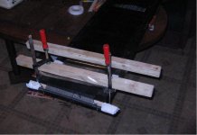
BillH said:Lukas, looks good so far. That's a good idea you had for stretching - simple and effective. Have you seen much flex in the threaded rod?
Hi,
The threaded rod flexed slightly together with wooden stick.
However , now i see that 9 cm gaps between support points are probably too wide.I don't know if electrostatic force will be strong enogh to bow wires.I am afraid that this effect could cause capacitance to vary , depending on field strength and therefore increase distortion.
I will probably try to divide 9 cm support points into 4 cm ones.
Regards,
Lukas.
4 cm that's almost 1 5/8 inches
Lukas: That is still a big gap for a small gage wire. Acoustat used 24 gage stranded wire with a heavy build PVC dielectric for thier stator wires (fairly stiff stuff) and chose to use the smallest size commercial egg crate louvre available which is a 1/2 inch open grid (2.5 cm across). I am sure that they looked into larger size louvres before deciding on the 1/2 inch format. With smaller gage wires hand tensioned I would think that you could go up to 3/4 inch cube but the wires will not be as well supported and the grid not as rigid so I don't see any advantage to going larger than a 1/2 inch spacing. Light louvre with 1/2 inch cubes at 3/8 inch thickness make a nice panel. The material is easy to obtain and inexpensive. This can save you a lot of work building your own grid to wind your stator wires on. I use a 30 gage magnet wire (specific type) and find that this works very well. I have used Testers model cement glue, thier non toxic (citrus based version) and also used Acoustat's method and assorted epoxy glues. I have even tried some UV cure adhesives but these are not practical for home based diy construction.
Bill: thanks for the tip on the adhesive but I am not thrilled to use epoxy adhesives either. Will see how my time works out this summer and see if I can play with the weldbond. Regards Moray James.
Lukas, I was ready to ask you how large a wire you were using in your last picture. I zoomed in and thought I saw string instead of wires.  Is it your wires?
Moray James, what adhesive method do you like the best so far? If there's a next set of ESL speakers for me, I'd like to try the wires on egg-crate louver. How do you tell an acrylic and styrene louver apart?
Is it your wires?Moray James, what adhesive method do you like the best so far? If there's a next set of ESL speakers for me, I'd like to try the wires on egg-crate louver. How do you tell an acrylic and styrene louver apart?
Follow those before
Hey Bill: would have to say that Acoustats method was by far the best and cost was reasonable. The Methylene Chloride really melts itself into the Styrene. You don't ever have to worry about glue bonds popping off as you have a chemical weld.
The Acrylic will be about three times the cost of the Styrene. You will need to use a different solvent and off of the top of my head I cannot remember the model number but it is made by Weldon. The Acrylic louvre is a creamy white and it is far stronger and heavier than the bluish white Styrene. You will probably have to special order your louvres in Acrylic so I dont think that you will have to worrie about getting them mixed up. With a piece the same size of each type in your hands the Acrylic is the one you would rather use, it's that obvious. Best regards Moray James.
Hi,
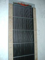
this is a Pic of my first stator.
Used 5mm PVC and 2*10mm aluminium strips. Added wooden strips between the aluminium bars for stability reasons and to have a flat mounting surface. The wires (1.5mm²) is glued to the alu-bars. This gave a spacing of 5mm(PVC) - 2.7mm(wire-diameter) = 2.3mm airgap.
the alu.bars are spaced app. 100m apart which is ok for a wire that thick, but spacing should be reduced for thinner wires. Between every bar and the diaphragm is a soft strip spacer. These thick wires don´t need mechanical tension, so after straightening they´re just glued to the frame.
jauu
Calvin
Attachments
BillH said:Lukas, I was ready to ask you how large a wire you were using in your last picture. I zoomed in and thought I saw string instead of wires.
Hi,
I used 0.8mm diameter(copper) wires.With PVC it is approx 2 mm.
Moray james :
I would surely go for light louvres, but i don't know where to get it.
Tried to find it , but unsuccessfully
.I live in Lithuania , and i think it isn't popular here.
Regards,
Lukas.
Hi Lucas,
look here, if you find something you like
http://www.alc-louver.com/gpages/germain.html
maybe i can get it and send it to you?
Regards,
Frank
look here, if you find something you like
http://www.alc-louver.com/gpages/germain.html
maybe i can get it and send it to you?
Regards,
Frank
- Status
- This old topic is closed. If you want to reopen this topic, contact a moderator using the "Report Post" button.
- Home
- Loudspeakers
- Planars & Exotics
- Wire stator gluing method