Quote: don't you think that 0.5mm PVC insulation will have higher dielectric strength , so higher bias voltages would be possible ?
Also , I think, the support points can be farther away for thicker PVC insulated wires.
I would like to ask , what size of wire acoustat uses , and what is their d/s spacing ?
1) I don't want to get into a debata as to what dielectric sounds best or whether or not the dielectric should be leaky. I posted this simply to discuss a means of easily bonding wires to a substrate.
2) The typical break down voltage for the wire that I discribed is 12,200.00 volts For further details look up Essex GP/MR-200 copper magnet wire.
3) heavier wire and its dielectric will require more structural support due to thier higher mass. Either way they can both be made to work well on a half inch grid.
4)Acoustat used a 24 gage copper stranded wire with a heavy build PVC dielectric. spacing between the diaphragm and the top surface of the dielectric was approx 1/16 inch.
5) I think that you are making an assumption that open are "needs" to be as high a percentage as possible for best performance. I don't believe that is the case. I think that closer spacing is necessary for higher eficiency as well as for immproved damping. That's just my opinion again. Hope that this hepls answer your questions. Best regards Moray James.
3) heavier wire and its dielectric will require more structural support due to thier higher mass. Either way they can both be made to work well on a half inch grid.
I'm sure the last statement is correct, but don't follow the first one. Heavier wire should be both stiffer and have greater inertia. Both of those properties should make the wire less prone to move as a result of the electrostatic force between the wires and the diaphragm (or between the wires in one stator and the wires in the other). If it's true that the heavier wire is less prone to move, couldn't you get away with more widely spaced supports?
Moray James: I'm having trouble locating a source of the Essex GP/MR-200 copper magnet wire. Any hints on a supplier?
I think that you are making an assumption that open are "needs" to be as high a percentage as possible for best performance. I don't believe that is the case. I think that closer spacing is necessary for higher eficiency as well as for immproved damping.
I agree that maximum open area won't lead to maximum performance; neither will minimum open area. At one extreme there's too little force on the diaphragm, and too little uniformity of that force. At the other extreme there's more force but no way for the sound to radiate. Where does the happy medium lie? The 50% open area mark is usually offered as the optimum value but I've not yet seen a good justification for that number. I'd be very interested if anyone can direct me to one. Some companies use the acoustic resistance from a layer of fabric to damp diaphragm resonances. That seems to suggest that Moray James' idea is right--you might as well damp the resonance and increase the field strength at the same time by leaning toward more closely spaced stator wires.
On a related note, I was reading the Martin Logan site today and they claim to have increased their panels' effectiveness by using a greater number of smaller holes in their perforated stators. I don't know what the initial or new percentage open area values were, but I found it interesting. On the other hand, their description of the operating principle for their magnet-based non-electrostatic drivers claims that the magnets have opposite charges on the two faces which is why the charged diaghragm moves. That didn't do much for their site's credibility in my book. The "explanation" is in the caption in the right hand column at:
http://www.us.martinlogan.com/technology/atf_theory.html
Few
ESL structural ideas
If we are talking stranded wire with a dielectric as opposed to a solid wire or rod then added mass just means a higher Q resonance when it does happen. Since you can only apply so much tension (practically speaking) to your stator wire then it would make sense to use a smaller gage wire. Like I said though either method will work fine if excuited properly. Acoustats used a large heavily insulated wire on half inch louvre and they sound fine.
I think that in the old days it was assumed that the larger the open area the better. However with the advent of high strength dielectric (again no intention to argue the virtues of one alloy over another) people found that large open area might not actually be best. Just a guess on my part but I would say that somewhere between 35 and 40 percent open is probably in the ball park.
You will need to google "Sureriour Essex" then you will find the magnet wire which I spoke of. Best regards Moray James.
Spelling correction
Should have read Superior Essex.
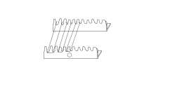
Your jig looks good. You can make a fine jig by using a width of threaded rod (half inch is a good thickness) across each end of your louvre. The rod needs to be set down (glued) into a block of wood (referenced into a slot) to keep it from flexing under tension of the stator wire. On the back side of the block (on a flat surface) you will need to place some hooks or screws with a head about every inch across the width of the rod back about 2-3 inches from the block. These will act as anchors for your wire when you turn it around to lay your next string back in the opposite direction. The threaded rod is your wire guide and the pitch of the rod will set the number of wires per inch you will wind. So a twenty thread per inch rod will yield (you guessed it) twenty wires per inch. You can go up to the next standard of thirty two threads per inch if you want more wire density. Hand tension of the wire works well and you will get the hang of it quickly. After about an inch of winding you will need to move over to the next hook or the wires will start to slide up out of the thread groves. This process is fast and easy to do. This style of jig works best for long narrow stators like the ones Acoustat built. The wire is very inexpensive to buy. Just to make sure that you follow me think of the drawing you included where you were using the slots to space and wind the wire around. Well the threaded rod (horizontal) acts as the spacer for the wire but you obviously cannot use the thread grooves to wrap the wire around to change directions as they are not deep enough. Thats what the hooks or screw heads to the back side of the threaded rod are for they let you anchor the wire to change direction of your wind. The threaded rod just gives you a constant space between your windings. I hope that this makes sense I know that a picture would be much better but I have no idea how to do that on a confusor. Best regards Moray James.
Should have read Superior Essex.
Your jig looks good. You can make a fine jig by using a width of threaded rod (half inch is a good thickness) across each end of your louvre. The rod needs to be set down (glued) into a block of wood (referenced into a slot) to keep it from flexing under tension of the stator wire. On the back side of the block (on a flat surface) you will need to place some hooks or screws with a head about every inch across the width of the rod back about 2-3 inches from the block. These will act as anchors for your wire when you turn it around to lay your next string back in the opposite direction. The threaded rod is your wire guide and the pitch of the rod will set the number of wires per inch you will wind. So a twenty thread per inch rod will yield (you guessed it) twenty wires per inch. You can go up to the next standard of thirty two threads per inch if you want more wire density. Hand tension of the wire works well and you will get the hang of it quickly. After about an inch of winding you will need to move over to the next hook or the wires will start to slide up out of the thread groves. This process is fast and easy to do. This style of jig works best for long narrow stators like the ones Acoustat built. The wire is very inexpensive to buy. Just to make sure that you follow me think of the drawing you included where you were using the slots to space and wind the wire around. Well the threaded rod (horizontal) acts as the spacer for the wire but you obviously cannot use the thread grooves to wrap the wire around to change directions as they are not deep enough. Thats what the hooks or screw heads to the back side of the threaded rod are for they let you anchor the wire to change direction of your wind. The threaded rod just gives you a constant space between your windings. I hope that this makes sense I know that a picture would be much better but I have no idea how to do that on a confusor. Best regards Moray James.
Hi
@Moray:
You mentioned Superior Essex.....which Wire do You mean? While standard wire will work, there are special types with very promising insulations. The best suited wire the Ultrashield will probabely not be cheap..if You can get it in small quantities anyhow.
The same is for EKS Multogan CR...
Investigations gave, that this kind of wire is seldomly produced and nearly impossible to obtain below 250kg.
jauu
Calvin
just a twist on an old idea
This is really just a twist on an old idea. Acoustat used this "encapsulation" method for all thier panels. They simply dissolved the base louvre material into solvent (methylene chloride) to form a thick syrup like liquid which they then ran across the PVC insulated wires at each horizontal point of the grid. Note that they used a machine to do this. I have used that exact same method (but done by hand) and it works well but is time consumming. The persent idea simply saves a lot of time and actually sticks to the wire insulation where as the Acoustat method was one of encapsulation only. Perhaps you were placing too much tension on your wire? I have found that you only need enough tension to keep the wire flat across the surface of the louvre.
The wire that I am using is made by Superior Essex and is the GP/MR - 200 series of copper magnet wire. This wire has a polyester base dielectric with a nylon top coat and can be purchased at an electric motor rewinding supply shop. This sounds (to me) better than the well aged Acoustat panels that it has replaced. While there may well be better dielectrics out there this is available and inexpensive and easy to use. Since this sounds at least as good as the PVC wire that Acoustat used (and is a far stronger dielectric) I don't see why the average diy type should be putting off building stators using this method. This material will yield an excellent quality panel which can be used as a base reference for any later found (superior) materials. As far as I can see the only real drawback to building wire stators on louvre has been that each and every contact point between the wire and the louvre has to be bonded so it does not rattle however doing this by hand that is a rather slow proceedure. Once done though this method resuts in excellent quality long lived panels. The method that I have suggested will save most all of the bonding time leaving the most tedious task that of actually winding the stator wire which is not really bad at all. There are other methods of doing the same thing such as precoating a layer of epoxy adhesive onto the louvre and then dropping the louvre down onto the pre strung stator wires. This method will yield excellent results but is slower and frankly I just don't like working with a lot of epoxy. so each to his own. I think that wire strung stators on egg crate light louvre are faster easier and less expensive to make than perf metal stators. But of course that is just my opinion. I would like to see a method that was totally safe (non toxic) for the diy builder to use on his kitchen table. This may well infact be possible using PVA adhesives like Weldbond. Someone may wish to give this a try on a trial panel. I like to wind the wire stator on top of the louvre. With a clean properly preped (sanded) louvre with the wires in place mist wit a 5 parts water 1 part Weldbond mixture (this acts as a primer) and let dry. Then run a thin bead of full strength weldbond across each horizontal rib of the louvre. Let dry. This should work well but please not that the dilute primer coat is critical to the weldbond sticking. While this method is slow (slower than epoxy) it should work and is totally 100 % safe and non toxic. Just a thought . Best regards Moray James.
This sounds (to me) better than the well aged Acoustat panels that it has replaced
James, can you elaborate a bit on the actual sonic improvements that you noticed? What are you using for diaphragm coating as well?
Take care,
Doug
what I noticed
Well I think that the primary reason for the improved sound was one of field strength. The Acoustat uses about 6 wires per inch and the jig that I use has twenty per inch. The new panels sounds more dynamic and the bass is deeper. This with the exact same DuPont HS65 Mylar diaphragm material as used in the Acoustat. Diaphragm coating is Licron.
Seems to me there are few diy types who are actually willing to experiment all that much. Most seem to want a working recipe which boasts results superior to any commercially product. Problem is that by the time you have worked that hard to figure all that out so well you would have to be crazy to give it away for free when you could go into business for yourself. I will probably end up trying the Weldbond idea myself before anyone else does. Regards Moray James.
wire stator jig idea
Here's an idea for a jig:
Take a long board a little longer and wider than the stators you are trying to build. At two opposing edges of the board, glue the threaded metal rod for spacing guides as discussed above. Then wind the wire around both sides of the board using the threaded rods as your spacing guides. Now the board will have spaced wires on both sides, so you are ready to make two stators.
I haven't tried it yet.
John G
excellent idea
Take a long board a little longer and wider than the stators you are trying to build. At two opposing edges of the board, glue the threaded metal rod for spacing guides as discussed above. Then wind the wire around both sides of the board using the threaded rods as your spacing guides. Now the board will have spaced wires on both sides, so you are ready to make two stators.
This sounds like an excellent idea. You could set it up so that the stators could be edge clamped into place on both sides of the board and then wind right over top of both of them in place. It would be a good idea for ease of handling while winding if you could also set it up on a central axis so the whole jig could be rotated around 360 degrees. Also unless you want to terminate a million wires to terminate to place the threaded rod at the narrow ends of the louvre such that the stator wires run the length rather than across the width of the louvre. You could then spray bond the wires in place and leave both stators on the jig until everything has set up.
Thanks for the good idea. Best regards Moray James.
Hi,
Thanks for all of your suggestions.
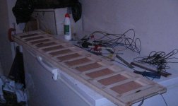
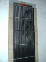
Here is the picture of frames that i am building.
The size of frame is 150cm x 28 cm.
I tried to strech one wire(Pvc coated , 2mm outter diameter, 0.5mm copper).The wire resonates like a string.If i press it with fingers at support points , part of wire still resonates , but at higher frequency.Is it possible to avoid this ? I think some kind of damping should help , is there any simple technique to do this ?
Sorry for poor picture quality , i had to recompress it.
Regards,
Lukas.
Thanks for all of your suggestions.
Here is the picture of frames that i am building.
The size of frame is 150cm x 28 cm.
I tried to strech one wire(Pvc coated , 2mm outter diameter, 0.5mm copper).The wire resonates like a string.If i press it with fingers at support points , part of wire still resonates , but at higher frequency.Is it possible to avoid this ? I think some kind of damping should help , is there any simple technique to do this ?
Sorry for poor picture quality , i had to recompress it.
Regards,
Lukas.
Attachments
Straightness
Hi Folks,
my first panels were wire stators, using standard PVC insulated H07-VU wire. I used a method to straighten the wires, that gave perfectly straight wires, but was a helllot of work, because each and every wire had to be straightend alone. It took me app. 1min per wire and I used just 42 wires per stator. That was the main reason to change to perforated metal stators....less time consuming work.
I wondered about a quick method to get the wire perfectly straight as Audiostatic does.
I assume that just pulling at the wire will not give perfectly straight results but leaves some kinks. So the wire has to be bend slightly several times or be drilled under tension.
Any suggestions?
jauu
Calvin
Attachments
Hi Calvin,
You van get splendid results by pulling the wires with human muscle force. I made curved wire stators this way and like you said, it is an awful job. I had to pull more than 60 wires straight each stator. A nice exercise!
You have to treat the wire very carefully to avoid wrinkles. So a laid the stretched wires on the floor, taking care not to bend the wires. I used very moderate tension on the wires just before attaching them to the stator. Since the wires are cut after being attached, most of the tesion has gone. I have not seen any twisting or bending of the stators afterwards.
Re: Straightness
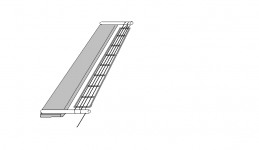
Hi ,
What do you think about this principle ?
Regards,
Lukas.
Calvin said:Hi Folks,
my first panels were wire stators, using standard PVC insulated H07-VU wire. I used a method to straighten the wires, that gave perfectly straight wires, but was a helllot of work, because each and every wire had to be straightend alone. It took me app. 1min per wire and I used just 42 wires per stator. That was the main reason to change to perforated metal stators....less time consuming work.
I wondered about a quick method to get the wire perfectly straight as Audiostatic does.
I assume that just pulling at the wire will not give perfectly straight results but leaves some kinks. So the wire has to be bend slightly several times or be drilled under tension.
Any suggestions?
jauu
Calvin
Hi ,
What do you think about this principle ?
Regards,
Lukas.
Attachments
easy does it
I think that the idea that John G proposed is just about as easy as it gets. In fact if you wanted to you could place two egg crate stator panels back to back fixing them so they cannot move. Then you cauld fix a wiring jig consisting of a section of threaded rod set into a piece of wood along each (narrow) end of the two stator panels. Then you simply wind the magnet wire round and round till you are done. With 28 or 30 gage wire hand tension is more than enough to result in wires that lay dead flat over the egg crate ( a small bow in the middle of the stator panels insures excellent wire to stator contact). This is somewhat awkward to handle but not overly so. I cannot imagine how winding could be more simply done (easier bu not more simply). I do like the jig that I described as it allows for excellent control of the winding process and you can stop for a break any time you like. That said if you want simple then John's suggestion is fine. Regards Moray James.
I think that the idea that John G proposed is just about as easy as it gets. In fact if you wanted to you could place two egg crate stator panels back to back fixing them so they cannot move. Then you cauld fix a wiring jig consisting of a section of threaded rod set into a piece of wood along each (narrow) end of the two stator panels. Then you simply wind the magnet wire round and round till you are done. With 28 or 30 gage wire hand tension is more than enough to result in wires that lay dead flat over the egg crate ( a small bow in the middle of the stator panels insures excellent wire to stator contact). This is somewhat awkward to handle but not overly so. I cannot imagine how winding could be more simply done (easier bu not more simply). I do like the jig that I described as it allows for excellent control of the winding process and you can stop for a break any time you like. That said if you want simple then John's suggestion is fine. Regards Moray James.

- Status
- This old topic is closed. If you want to reopen this topic, contact a moderator using the "Report Post" button.
- Home
- Loudspeakers
- Planars & Exotics
- Wire stator gluing method