People did design good and bad crossovers before CAD and Vance Dickason. All you need is graphs of the driver responses and impedances paper, pencil and calc [and an understanding of reactance and resonance]. If you choose the levels of the drivers, follow the rules of phase difference etc. there is no need to measure. The obscession with measuring DIY loudspeakers has grown with the gadget fetish of computers. Before the FFT computer algorithm became used first in the 70's for testing - and not widespread until the last 10 years, it was very impractical to test loudspeakers because of their surrounding room, and only the richest manufacturers could get reliable data [which means little when you put it in a domestic room anyway] but people still designed good ones by using xover maths and driver data.
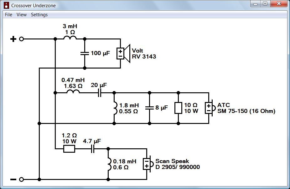
That Wilmslow xover is naff and if you were designing from scratch with an ATC mid datasheet, you could avoid the 100u, since the whole mid needs attenuation anyway which gives some flexible choice. As long as your total xover doesn't stress the amp with low ohms anywhere.
That Wilmslow xover is naff and if you were designing from scratch with an ATC mid datasheet, you could avoid the 100u, since the whole mid needs attenuation anyway which gives some flexible choice. As long as your total xover doesn't stress the amp with low ohms anywhere.
But how do you confirm that you've done everything ok without measurements? Your ears maybe? I've lost count of the amount of times i've heard this - Quote "I've now finished the crossover and these speakers sound amazing BUT the odd track doesn't sound that good. I guess it's recording quality or the revealing nature of the speakers that's causing the problem etc etc"
You can think that with any speaker design, commercial or DIY. No speaker has a flat frequency response, they are all just joined together wobbles. The frequency response of your speakers listening to any studio recording should actually be:
((your hearing)*(your room))/((the guy doing the mixing's hearing)*(his room)*(his speakers))
((your hearing)*(your room))/((the guy doing the mixing's hearing)*(his room)*(his speakers))
Well, of course! It's all in the mathematics.
I am not a ******** merchant.
Hi,
That is a matter of opinion. Spouting about Steen Duelund
and claiming a lecture on String and M theory has anything
to do with dome tweeters and bass dustcaps is all pure BS.
People are hostile to pompous "know-it-all" BS, especially
when its not simple, but is oversimplified pontification.
rgds, sreten.
You grossly misunderstood and misinterpreted the torus compactification and Ricci-flat from the Susskind lecture.The implication of the mathematics that Lenny Susskind does with waves on a sphere, is that waves on a toroid work better. Hence Vifa XT25 ring-radiators and cone tweeters might sound better. Take it or leave it. I couldn't care less what you do, Sonce. I know what I prefer.
Ring radiator has nothing common in topology with torus (toroid). Ring radiator topologically is identical to a dome or a cone. And cone is very similar to the inverted dome even to the untrained (in topology) eye. Your preference of the sound of ring-radiators has no ground in mathematics of String Theory.
Last edited:

Get measuring equipment, measure the drivers and put the measured data in the crossover simulator. Simple as that. Everything else ("generic crossover", using other drivers data in the simulator, etc) is just plain wrong.
You can lead a horse to water but you can't make it drink.
Dissi, what values of L1 and C1 to reduce the SPL hump would you recommend please?
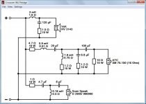
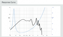
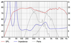
The original filter has a coil made of thin wire with a resistance of perhaps 1.6 ohm (guess) and a 1.5 ohm resistor in series to the shunt capacitor. Both resistors do help to damp the resonance. Attached is a zip file containing a generated impedance data file (RV3143.zma). Import it in Boxsim and then your simulation will show the hump also.
What is the simulation response with the original network?
Well, that's exactly what I have tried to avoid so far.
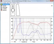
The reason is that driver data are quite unsure. Volt provides a data sheet for the woofer, but I don't think the published SPL curve is reliable and the level is correct. Even worse the ATC mid. Just some TS-parameters, but no response curves at all.
Nevertheless I do attach my simulation result since there has been a lot of discussion about the quality of the original WA crossovers. The response curve of the mid is derived from Zaph's measurement of the S version of the driver. The woofer is a slightly corrected version of the data sheet. Hence consider the simulation only as a rough approximation. Thanks.
Attachments
How right you are. Gotta love it!You can think that with any speaker design, commercial or DIY. No speaker has a flat frequency response, they are all just joined together wobbles. The frequency response of your speakers listening to any studio recording should actually be:
((your hearing)*(your room))/((the guy doing the mixing's hearing)*(his room)*(his speakers))
I never take bafflestep ideas seriously. It's just bassier or less bassier as you change the coil, and the room gain does more below 300Hz. Flat frequency response on-axis is overrated. I think you hear power response around the room more in practise.
Good modelling contribution from Dissi there. I followed that. It's not rocket science that a high inductance 12" paper VOLT RV3143 woofer needs some shunt resistive damping to avoid a peak in response. It actually looks like it has natural rolloff around 700Hz, which is useful. And upping mid level also looks good and justified.
So Jim, I think you need a 1.5R or 2.2R resistor back on the bass filter shunt. 100uf or 120uF is neither here nor there. Not much difference IMO, unless someone wants to argue about it!
Attachments
I think it is perhaps more of an issue with the kind of person that is attracted to the WA Prestige speaker kit combined with the problems that seem to have evolved recently at WA.Is there a curse on wilmslow 3 ways?
The cabinet is a reasonably distinctive looking home audio design rather than a simple rectangular box that those with more of a "pro" interest would be likely to opt for. It is modestly priced but has a large surface area with neither significant stiffness nor significant damping. It would need a fair amount of work to bring it up to the performance more typical of speakers at this price level but the price asked is fine for what it is.
The crossovers are both passive and basic with little to no compensation for baffle and driver characteristics. In the other thread WA claimed their crossover for the Volt midrange should have a high pass crossover frequency below it's resonant frequency which is not sensible (they also claimed katieanddad's defective crossover was not defective after looking at it which is unacceptable). Although easy enough to fix these days with a bit of time, money and interest a speaker at this price level would usually be expected to have a reasonably sophisticated crossover and not a possibly defective basic one.
The drivers used are pretty much the most expensive sold by WA. The woofer and midrange are good studio-type drivers rather than ones more optimised for home use. Apart from the price which is out of step with the crossover and cabinet (or vice-versa) the combination seems fine.
According to a poster considering the purchase of WA this type of kit is a significant part of the business and so they are getting bought. I suspect the OP for this thread and the previous one are more representative of their customers rather than regulars on DIY speaker forums. If WA returned to providing a competent basic crossover in the way they did in the past (I am guessing the current problems have arisen because they currently consist of non-technical sales person/people) I suspect the small number of unhappy owners would disappear from diy sites and remain happy on audiophile forums where there is an outlook more aligned with their own.
Whatever, it makes for an interesting thread now and again.
Always good to have a review.
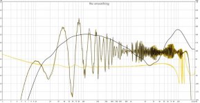
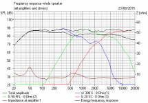
I had a look at KatieandDad's rough measurements on the original troublesome filter which led to my ideas on a fix.
Below is the K&D measurements and mine and Dissi's sims, and bear in mind K&D's comments of a midrange that lacks energy and sparkle.
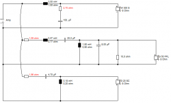
You are quite close to where you want to be now, IMO. Fix that bass shunt. I notice you've upped the 6.8uF to 8uF which is heading in the right direction too. Losing the 4.7R on the mid input altogether is perhaps a bit too dramatic IMO, I would have tried 2.2R myself,especially to keep impedance up. But it's your project.
It takes a while to evaluate a speaker IMO. Give it a good long listen.
I had a look at KatieandDad's rough measurements on the original troublesome filter which led to my ideas on a fix.
Below is the K&D measurements and mine and Dissi's sims, and bear in mind K&D's comments of a midrange that lacks energy and sparkle.
You are quite close to where you want to be now, IMO. Fix that bass shunt. I notice you've upped the 6.8uF to 8uF which is heading in the right direction too. Losing the 4.7R on the mid input altogether is perhaps a bit too dramatic IMO, I would have tried 2.2R myself,especially to keep impedance up. But it's your project.
It takes a while to evaluate a speaker IMO. Give it a good long listen.
Attachments
Yup, it imports into the driver data of the woofer into impedance.Great. I can't see how to import the posted .zma file into Boxsim
Anyone done it?
But it doesn't really help. Ideally you'd also have the FRD frequency response plot and a few other items too.
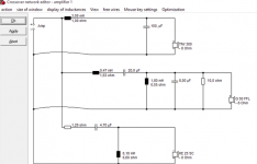
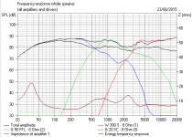
I did my usual "BS" rough and ready stuff with Dissi's ZMA here. It's just upping Le inductance really. I can do that in my head.
IMO, with only 3 variables to play with on the bass filter, 3mH, 100uF and a resistance anywhere between 1.5R and 2.7R just does the usual tradeoffs. There isn't a perfect answer. 4mH doesn't look any better. A higher order filter is indicated. We're not gonna do that.
http://www.diyaudio.com/forums/multi-way/210627-wilmslow-audio-prestige-platinum-72.html#post4326410
Beyond some point you are just fiddling about. FWIW, I think my generic filter, bass section for a different woofer aside, is rather good. Yours has ended up little different. The science always wins.
Attachments
Last edited:
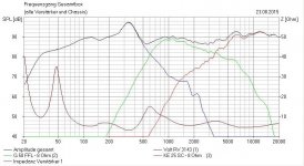
After creating .zma files for my drivers amplitude and impedance response using SplTrace I think I have finished the crossover. I have massaged the crossover to reduce the hump that comes from the top end of the Volt 12" bass driver and the overall response seems OK.
The next step is to move the crossovers back inside the speakers and wire up using some decent silver plated OFC cable and bin the external boxes.
Many thanks to the people who made a positive contribution to this thread.


The next step is to move the crossovers back inside the speakers and wire up using some decent silver plated OFC cable and bin the external boxes.
Many thanks to the people who made a positive contribution to this thread.
- Status
- This old topic is closed. If you want to reopen this topic, contact a moderator using the "Report Post" button.
- Home
- Loudspeakers
- Multi-Way
- Wilmslow Audio Prestige Gold. Crossover help.