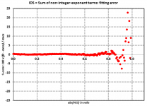
Iv'e attached CSV files that contain 345 rows; a header row and then 344 JFET datapoints. Each datapoint contains VGS, IDSmeasured, IDSfitted, %error, and dIds/dVgs at that VGS.
%error = 100 * (fittedIDS - measuredIDS) / measuredIDS
Since they're CSV format, you can open them with Excel and plot the data just by clicking on the columns.
Fitted coefficients for the 8th order polynomial (with integer exponents) were
Fitted coefficients for the sum of non-integer-exponent terms (see post # 177) were
i.e. the exponents were 0.974, 2.111, 5.840, and 8.159.
%error = 100 * (fittedIDS - measuredIDS) / measuredIDS
Since they're CSV format, you can open them with Excel and plot the data just by clicking on the columns.
Fitted coefficients for the 8th order polynomial (with integer exponents) were
$coeff[0] = 1.3052375e-002 ;
$coeff[1] = -2.4183103e-002 ;
$coeff[2] = 8.4007222e-003 ;
$coeff[3] = 2.4333184e-003 ;
$coeff[4] = -3.5186917e-003 ;
$coeff[5] = 1.6250984e-003 ;
$coeff[6] = 5.5941643e-003 ;
$coeff[7] = 8.6130102e-004 ;
$coeff[8] = -4.2619386e-003 ;
$coeff[1] = -2.4183103e-002 ;
$coeff[2] = 8.4007222e-003 ;
$coeff[3] = 2.4333184e-003 ;
$coeff[4] = -3.5186917e-003 ;
$coeff[5] = 1.6250984e-003 ;
$coeff[6] = 5.5941643e-003 ;
$coeff[7] = 8.6130102e-004 ;
$coeff[8] = -4.2619386e-003 ;
Fitted coefficients for the sum of non-integer-exponent terms (see post # 177) were
$coeff[0] = 1.3088344e-002 ;
$coeff[1] = -2.2937478e-002 ;
$coeff[2] = 9.7438075e-001 ;
$coeff[3] = 7.6904537e-003 ;
$coeff[4] = 2.1116741e+000 ;
$coeff[5] = 5.1756029e-003 ;
$coeff[6] = 5.8400235e+000 ;
$coeff[7] = -3.0127659e-003 ;
$coeff[8] = 8.1590383e+000 ;
$coeff[1] = -2.2937478e-002 ;
$coeff[2] = 9.7438075e-001 ;
$coeff[3] = 7.6904537e-003 ;
$coeff[4] = 2.1116741e+000 ;
$coeff[5] = 5.1756029e-003 ;
$coeff[6] = 5.8400235e+000 ;
$coeff[7] = -3.0127659e-003 ;
$coeff[8] = 8.1590383e+000 ;
i.e. the exponents were 0.974, 2.111, 5.840, and 8.159.
Attachments
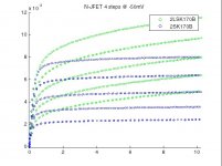
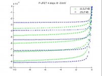
I/V Curve trace results of my Linear Systems LSK170B / LSJ74B (Thanks Jan Didden!) vs. Toshiba 2SK170 and 2SJ74:
.
-- xLoff
Wow is the lambda (output impedance) of the LSK parts that bad? Transistormarkj, what values for the model parameters does this give?
More or less 5k?
Right, Early voltage looks to be only 50V or so. Without cascodes these would behave very differently from the Toshibas. OTOH they are more triode like.

Oh, I don't know, folks seem perfectly happy to simulate distortion using LTSPICE BJT models, whose output conductance is similarly limited to a perfectly straight line with no curvature (d2Ice/d2Vce = 0).Also there's not much hope of getting a sim to match real distortion performance, just the basics.
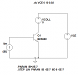
Here's the BC550C BJT model from the Cordell website
Attachments
Right, Early voltage looks to be only 50V or so. Without cascodes these would behave very differently from the Toshibas. OTOH they are more triode like.
That's the spirit!! Although most of this is way over my head, my intuition tells me that people are concentrating too much on whether they are identical to the toshiba's and less on what the implications for real world applications will be
Sure it might be a bit different, but can those differences be used to advantage, rather than be a hindrance? Tony.
Here's the BC550C BJT model from the Cordell website
It follows a real Philips BC550C nicely (marked PH7 3 with HFE 535).
Attachments
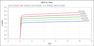

Oh, I don't know, folks seem perfectly happy to simulate distortion using LTSPICE BJT models, whose output conductance is similarly limited to a perfectly straight line with no curvature (d2Ice/d2Vce = 0).
Here's the BC550C BJT model from the Cordell website
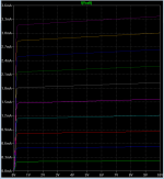
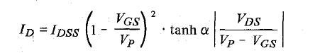
The Level 1 JFET model deviates grossly from reality for these short channel FET's, which folks like to use in simple open-loop or minimum feedback circuits. Over much of their range bipolars are far closer to a straight line. BTW I couldn't get that extra JFET parameter in LTSPICE to do anything useful. The level 3 model uses the tanh fitting parameter (pic).
Attachments
Last edited:
Yep, a standard kludge people use to make long channel models, kinda sorta fit the behavior of short channel transistors, is to insert a source resistance. This causes the saturation knee voltage "VDSsat" to grow more slowly, and kinda sorta emulates carrier velocity saturation. When you go past the knee and get into the saturation region proper, the model will give a straight line with no curvature.
A fun project, maybe the scope of a bachelor's thesis, would be to build a simulation macromodel that combined a level1 JFET with a BSIM3 MOSFET, giving a 3 terminal black box with the same IV curves and same capacitances and same input impedance, as a short channel JFET.
A fun project, maybe the scope of a bachelor's thesis, would be to build a simulation macromodel that combined a level1 JFET with a BSIM3 MOSFET, giving a 3 terminal black box with the same IV curves and same capacitances and same input impedance, as a short channel JFET.
Yep, a standard kludge people use to make long channel models, kinda sorta fit the behavior of short channel transistors, is to insert a source resistance. This causes the saturation knee voltage "VDSsat" to grow more slowly, and kinda sorta emulates carrier velocity saturation. When you go past the knee and get into the saturation region proper, the model will give a straight line with no curvature.
A fun project, maybe the scope of a bachelor's thesis, would be to build a simulation macromodel that combined a level1 JFET with a BSIM3 MOSFET, giving a 3 terminal black box with the same IV curves and same capacitances and same input impedance, as a short channel JFET.
Except with these FET's more than 25 or so Ohms mucks up the noise. I would make a "noiseless" resistor with a VCCS feeding back on itself, give it a poly function maybe you could get a great fit (thinking out loud).
I use this trick to make noiseless filters in sims.
Scott,
Send you a email via the forum.
Take a look at US2011228954A1.
Cheers,
Patrick
I left an answer over in the other thread.
I would make a "noiseless" resistor with a VCCS feeding back on itself, give it a poly function maybe you could get a great fit (thinking out loud).
Mike Engelhardt, author of LTSPICE, seems to say that behavioral sources have an exploitable bug: they simulate noiselessly. See msg # 11349, 02 Aug 2006: Yahoo! Groups
Simulations with JFET´s have never been useful as circuits I have connected up and performs like expected do not simulate correct, and some of my circuits cannot be simulated at all without adding extra virtual components in the simulation circuit, but still not giving a result that have any real relation to the physical circuit.
Wow is the lambda (output impedance) of the LSK parts that bad? Transistormarkj, what values for the model parameters does this give?
Hi,
Could you or someone expand on this a bit for my education? Are you simply referring to "output impedance" as the inverse of transductance, or as a different parameter? And if a different parameter, what in the curves reflects the output impedance? If I sound confused, it is normal. Thanks.
- Status
- This old topic is closed. If you want to reopen this topic, contact a moderator using the "Report Post" button.
- Home
- Amplifiers
- Pass Labs
- Will linear deliver on promised lsj74