Is there any reason why we should not use schottky diodes at the bridge rectifier on a normal 240V AC power supply but rather use the 1N5400 series, or the 6A20G or similar? The silicon diodes will drop more voltage so will spend more power and will get hotter and we will get less DC voltage. The schottkys have more reverse current, but I am not sure how to factor that in. This is not a switched mode, so the frequency on the diodes will be sinusoidal at 50Hz.
So , why not schottkys ?
So , why not schottkys ?
Sure, schottkys have lower forward voltage and no switch-off issues. But they are relatively expensive compared to silicon, especially at higher PIVs. If forward loss is really the issue use sychronously driven MOSFETs, they may well turn out to be cheaper than big hulking schottkys.
It is alleged that Schottky diodes have negligible reverse recovery time. It is further alleged that Schottkys do not generate enormous dI/dt when they switch off, thus they do not stimulate oscillation of the transformer secondary's RLC resonant circuit. L=secondary, R=trafo core nonlinearity, C=secondary+rectifiers.
Me, personally, I purchased 100 pieces of MBR40250 (datasheet) Schottky diodes, just to be ready in case I ever needed a 40 ampere, 250 volt, Schottky diode. But I also bought some soft recovery "Stealth" diodes from Fairchild, and some Qspeed diodes from Power Integrations, and some Platinum Epixatial diodes from Vishay, some Hyperfast diodes from Fairchild, and even some Silicon Carbide diodes from Cree. So it's obvious that I ain't no role model for pinchpenny tightwads, frugal Scotsmen, or cost optimizers from the Netherlands. On the other hand, I do have measured empirical data. Those who don't purchase diodes, have opinions.
Me, personally, I purchased 100 pieces of MBR40250 (datasheet) Schottky diodes, just to be ready in case I ever needed a 40 ampere, 250 volt, Schottky diode. But I also bought some soft recovery "Stealth" diodes from Fairchild, and some Qspeed diodes from Power Integrations, and some Platinum Epixatial diodes from Vishay, some Hyperfast diodes from Fairchild, and even some Silicon Carbide diodes from Cree. So it's obvious that I ain't no role model for pinchpenny tightwads, frugal Scotsmen, or cost optimizers from the Netherlands. On the other hand, I do have measured empirical data. Those who don't purchase diodes, have opinions.
Imperceptibly, because that loss mechanism is at mains frequency (not tens or hundreds of kHz as per a typical smps).If switching losses are reduced, do they get less hot?
Fairchild Stealth 600, available in 4a, 8a, 16a, and the ever so convenient Fairchild Stealth Dual, are all popular for linear power supplies.
As for "sound of" aspects, I can't identify a particular sound based on the power supply diodes alone; however, some are awful, some are likable, and I like these.
Like fast silicon, snubbing is done with an RC across each secondary winding, (or simply a 2u x polyester capacitor across each secondary can work), although most applications that I have seen, don't show any snubbing in use.
Here's an example with Fairchild Stealth Dual (see attachment).
The 6a05's can also be replaced with Fairchild Stealth 600, 16a (the CRC's "R" is diode bypassed to reduce sag, aka increase dynamic punch).
I like this supply very much.
The ferrites (or a knot) and the MBR1645's (or more Stealth) actually belong, after the cable, at the edge of the amplifier boards, if possible.
Yes, it is dual mono with just one supply. Schottky are fun.
As for "sound of" aspects, I can't identify a particular sound based on the power supply diodes alone; however, some are awful, some are likable, and I like these.
Like fast silicon, snubbing is done with an RC across each secondary winding, (or simply a 2u x polyester capacitor across each secondary can work), although most applications that I have seen, don't show any snubbing in use.
Here's an example with Fairchild Stealth Dual (see attachment).
The 6a05's can also be replaced with Fairchild Stealth 600, 16a (the CRC's "R" is diode bypassed to reduce sag, aka increase dynamic punch).
I like this supply very much.
The ferrites (or a knot) and the MBR1645's (or more Stealth) actually belong, after the cable, at the edge of the amplifier boards, if possible.
Yes, it is dual mono with just one supply.
Schottky are fun. Attachments
![TankAndSmoothingNosag-DM[1].gif](/community/data/attachments/379/379010-9c1d58b7a99164cb3527e14cf5a78baa.jpg)
Last edited:
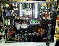
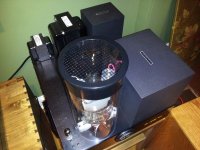
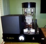
My Midlife Crisis mono amps use Cree SiC Schottky diodes. Each mono has Twenty 1200V in the 2.3kV output supply, four in the 450V driver supply. The 10V, 10A filament supply uses four 100V Schottkys. The 6.3V DC heater supply for the driver tube uses a single Schottky bridge (SMD).
So I guess we can say some DO use Schottkys in the PS!
So I guess we can say some DO use Schottkys in the PS!
Attachments
My Midlife Crisis mono amps use Cree SiC Schottky diodes. Each mono has Twenty 1200V in the 2.3kV output supply, four in the 450V driver supply. The 10V, 10A filament supply uses four 100V Schottkys. The 6.3V DC heater supply for the driver tube uses a single Schottky bridge (SMD).
So I guess we can say some DO use Schottkys in the PS!
Nice.
Link to pix of top side?
Nice.
Link to pix of top side?
Top Side Pics.
Attachments
Dan,
What is the diode doing?the CRC's "R" is diode bypassed to reduce sag, aka increase dynamic punch
Hello Mark.......On the other hand, I do have measured empirical data. Those who don't purchase diodes, have opinions.
So what have you found with your measurements ?.
Dan.
BTW, kudos on your Quasimodo design.
I still have more than two dozen diode types that I've purchased but haven't tested yet, so ... nothing to release for public consumption. Among the untested are the "Hyperfast" RHRP860 and the "Hyperfast-II" FFPF08H60S. I'm curious whether they differ from their "Stealth" bretheren.
Last edited:
Daniel
In your post #8 the C-R-C supply shown has +/- 16,500 uF before the resistors and +/- 3,300 uF after them. Wouldn't it be better the other way around for the following reasons:
1) having lower capacitance before the resistors will reduce charging currents and hence radiated RFI from the wiring.
2) having higher capacitance after the resistors will increase the low pass filtering effect, thereby reducing harmonics of the mains frequency.
Like AndrewT I don't get what purpose that diode in parallel with the resistors serves other than to drop the voltage slightly.
Last edited:
... the C-R-C supply shown has +/- 16,500 uF before the resistors and +/- 3,300 uF after them.
I think you might have misunderstood the schematic. AC from the transformer secondary is applied to the diode bridges on the right side, and DC to the Left and Right amplifier channels is taken from the left side.
Attachments
- Status
- This old topic is closed. If you want to reopen this topic, contact a moderator using the "Report Post" button.
- Home
- Amplifiers
- Power Supplies
- Why not Schottkys ?