I always have problem in my home sound system .. when I connect the '' personal video recorder '' to the sound system.
In my sound system I have a FM tuner using an outside antenna with a 75 ohm cable, and this antenna must be grouded for safety, a 4 feet pin in the ground, then the PVR is grounded on local cable distribution network.
The 2 ground of course dont match ! the typical ground loop problem.
This afternoon I was thinking of using an instrument amplifier to get some isolation and get rid of the hum & noise I get. So I desing this project ( below).
This amplifier should have his own power supply , for the input I will use shielded cable with RCA plugs to keep isolation betwen input and output, there will be only one pair of RCA jacks on the case for the output.
Should I build this amplifier ? or do you see a better solution ?
Sorry for my mis-search
No problems. Usually, with switchable input attenuators before them.
Should I build this amplifier ? or do you see a better solution ?
I guess it's worth a try!
use a shielded 2core for the input connection.This afternoon I was thinking of using an instrument amplifier to get some isolation and get rid of the hum & noise I get. So I desing this project ( below).
This amplifier should have his own power supply , for the input I will use shielded cable with RCA plugs to keep isolation betwen input and output,
Then your two enclosures are connected via the shield to attenuate the interference voltages between the chassis.
Use FM antena isolation transformer, or buy one. You have to think also about allowed CMV (common mode voltage) for such instrumentation amplifier. Signal source can not be fully floating. And in Your schematic is input DC level undefined , inputs are floating.Should I build this amplifier ? or do you see a better solution ?
Last edited:
No problems. Usually, with switchable input attenuators before them.
I choose to build one from Soviet 2P25T rotary switch with ladder of "Red Devil" resistors ( I know that you know what I mean
)> The 2 ground of course dont match ! the typical ground loop problem.
No, they SHOULD "match" for electrical safety.
Un-bonded, my cable and power are 1V-4V apart due to line drop.
After reading NEC, I jumpered the cable ground and the power ground, at the pole in my yard and also in the cellar. The TV stopped hum-barring.
Antennas must also be grounded for lightning safety. And they can/should/must(?) be bonded to the other household grounds. I will not try to explain the NEC (which may not be Code in your town) but this is a summary:
http://www.reeve.com/Documents/Articles Papers/AntennaSystemGroundingRequirements_Reeve.pdf
I also note that an "Intersystem Bonding Bar" is a thing, even sold here in Home Depot. I have one in my cellar, and plan another for a house I am working on.
A TL072 (or any op-amp you could afford) has NO chance of working at FM broadcast frequencies (!!!), and even if it did you certainly wouldn't use that circuit for it.Should I build this amplifier ? or do you see a better solution ?
A much better solution is in the first link of post #26, the RF transformer, or even the two-capacitor thing. If you use the two-capacitor schematic, put them in a metal box with one connector's ground connected to the box's case and the other connector's ground insulated from the box. The text says how it's still susceptible to interference, but it's easy (depending on your metalworking skills) to put the circuit into a small metal box for shielding.
PRR has a point (though grounding and bonding is really a rabbithole beyond the scope of this thread - consult local building wiring codes, contact a local Licensed Electrician, Attorney, etc.), but even with all that fixed, I'd still use isolation between the tuner and the antenna, just because.
Antenna is grouded by itself .... 4 feet of metal pipe in the groung, and the pipe is straight 25 feet long this is needed for safety. And the straight pipe give the lowest inductance possible ... a lightning is a very heavy charge with a very fast rise time.
The cable service have a lot of different groud all around They also feed 24 volts 60 hertz on the coax ... to feed power for amplifer & equipement on their net. Then it is grounded on the electric meter box close to the house.
Behind my sound system antenna cable & FM antenna coax are linked toghether with a grounding bus bar ( 1/4 inch thick copper bus bar ) and grounded at the power bar used to feed all my equipement ( all equipement are feed from the same power bar to keep them all on the same ground & same neutral ) ... and still a lot of noise ! ( note the PVR is build with a switching power supply ).
So I build the instrumentation AMP and now I did get rid of the noise.......
Maybe it is not tho most elegant solution bu it does the job.... and for the sound quality 3 more OP amp in the path .... I am not worried it is only television ... and they use MP3 for sound.
Now I have to work on a new problem, the instrumentation amp works perfectly and I have built a power supply for it.
Basic configuration: power transformer, full wave rectifier, electrolitics, LM7812 & LM7912, electrolytics and decoupling caps at input & output of regulators.
But the unit do not shut down quietly .... there is a strong oscillation while shutting down.
I there something i have missed ? or a trick I should know ?
Many circuits go nuts as their supply drops from 12V through a few V. That's why we have speaker muting relays.
You should not be having huge hum if all those grounds really are as you say. Therefore I have to wonder if there is a ground-fault and if it may be UNsafe.
However, this is your life. Use a transformer. There is a canned stereo transformer in most car-sound supply stores. Crutchfield's offering. I have used these (they all seem to come from just two Asian suppliers) and given low-Z drive they have very good bandwidth and DO break hum loops. These transformers will isolate over 100V kinda reliably (I designed one into a 150V tube limiter) so should be OK in Quebec (less sure about 230V lands).
Alternatively if the loop is via a high-level RF path (cable company) you can get RF transformers to put between the cable and the system. These do less/no damage to your audio but could cut the higher frequencies and you lose a few channels.
There is a canned stereo transformer in most car-sound supply stores. Crutchfield's offering. I have used these (they all seem to come from just two Asian suppliers) and given low-Z drive they have very good bandwidth and DO break hum loops. These transformers will isolate over 100V kinda reliably (I designed one into a 150V tube limiter) so should be OK in Quebec (less sure about 230V lands).
Did you measure them by chance? Do they have a static shield?
Edit: Never mind, I bought one. Will post details
Last edited:
They pass a couple V at 50Hz without gross bending, and run well over 15KHz.
The tradeoff is that they may not even be 600 Ohms impedance in low bass. Coming from typical opamp chips, not a big problem, certainly compared to buzz.
There are better transformers, such as Jensen, at much higher prices.
The tradeoff is that they may not even be 600 Ohms impedance in low bass. Coming from typical opamp chips, not a big problem, certainly compared to buzz.
There are better transformers, such as Jensen, at much higher prices.
The only point I can link to ground is the shield of the coax from the antenna or from TV distrbution, but the signal from TV distribution is fed from the amplifier at the limit of my backyard grounded on a lot of stuff ... power distribution .. basic telephonr wiring .. local ground from a steel pin in the ground ... a many others I dont know anything about .... this is wy I did go to a isolation amp ...
> thick copper bus bar
Good. All signal paths "must" bond together on the one bus. While you also want power grounds and chassis grounds bonded, those signal cables, especially from "outside sources", should bond here.
Google cable ground block.
Extreme example: RG6 Quad Cable Ground Block at SatPro Can't complain about 89 cents (shipping will be more). Is a bit bulky. Single and dual blocks are readily available. Add very short jumper cables (That store only has a 25-pack for $40. Does tell you that 18" cables must be needed in large quantity.)
Attachments
I found a grounding block on amazon UK. £5.80
My aerial cables come into the house many tens of yards/metres away from the electricity distribution board.
Should the grounding block be connected to the PE wires in the power sockets in the cupboard where they terminate?
The ring main uses ordinary 2.5sqmm+Earth. Not much area for conducting a lightning strike.
There is no route to run a thick copper tape back to the distribution board.
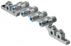
4-way ground block
4x F-female>4x F-female
nickle plated
My aerial cables come into the house many tens of yards/metres away from the electricity distribution board.
Should the grounding block be connected to the PE wires in the power sockets in the cupboard where they terminate?
The ring main uses ordinary 2.5sqmm+Earth. Not much area for conducting a lightning strike.
There is no route to run a thick copper tape back to the distribution board.
Attachments
Last edited:
I have a set of 3 transformers from a PA sound system voltage ratio is 1 to 1, and quick test at 400 hertz show that they can go up to 20 volts peak to peak before distortion or saturation, so at 20 hertz they shoud be able to work with 1 volt peak to peak .... so 0.7 volts RMS at 20 hertz. I am affraid it is a bit low, the output of the personal recorder may be a bit above this level.
The transformer are shielded 2.1 cm diameter and 2.3 cm tall.
The transformer are shielded 2.1 cm diameter and 2.3 cm tall.
- Status
- This old topic is closed. If you want to reopen this topic, contact a moderator using the "Report Post" button.
- Home
- Source & Line
- Analog Line Level
- Why not instrumentation amplifier?