carlosfm said:
Start collecting.
I have a very old cdp with one PCM56.
I take offers.
Sounds... yellow.
No wonder it sounds yellow
One chip for two channels
Thanx, too expensive shipping
I trade 1 TDA1541A used for 2 PCM56 used, anybody ?
rfbrw said:
And then what? Audio dacs that can cope with Fs at 2.8Mhz are a bit thin on the ground.
Bernhard said:
And linearity will improve with 64 per channel.
Yep, no argument there! Although you should be able to find non-audio DACs that can accept 2.8MHz and higher, with same or better linearity then TDA1541 and TDA1543.
Re: Re: Re: Re: On topic
So i found my books and had a look. This was too long ago for me, so i did the obvious: i asked around. So the effect is.... a FIR filter, so indeed nothing to do with interpolation (ray is right once again). Should have known, it WAS explained.
http://www.diyaudio.com/forums/showthread.php?postid=335744#post335744
Which leads to the conclusion that i swapped non-os and this fir filter. Listing/measuring at one while thinking it was the other. So a non-os dac is not as bad as i thought.... Mind you i never heard another one to compare and my measurement equipment is acient.
---oops---
So the curve i got from the non-os dac (which i thought was the 'oversampled' dac) can be explained by the non-os effect (i thought it was due to the transformer and buffer). And other curve going steep down at high freqs shows that one can build a fir filter this way
The maths give:
non-os: -0.8dB at 10kHz, -3.5dB at 20kHz
fir h=[1 1]: -3.5dB at 10kHz, -16dB at 20kHz.
Anyone for a filter?
So what is lost....?
Nothing much, only what was left of my pride
The experiment was only performed with some extra lines of code in the GAL, the dac was designed as non-os. This delaying was an add-on i did at a later stage. Am working on a cpld design for all logic and i remember i was suspicious about this non-os/delayed jumper when i was 'porting' the logic. Should have looked more into it then.
As a filter it is quite good: "a very good time-domain response with no ringing, and it will reduce aliasing distortion quite significantly." to quote the expert.
I'll look into compensating for the hugh rolloff in the analog domain, -2.5dB at 10kHz is v. audible.
Maybe then it is better than non-os
Oops, here i go again
guido said:
Have to dig up my books from 'digital signal processing' classes i had 10 years ago. Must be possible to put this into formulas.
So i found my books and had a look.
This was too long ago for me, so i did the obvious: i asked around. So the effect is.... a FIR filter, so indeed nothing to do with interpolation (ray is right once again). Should have known, it WAS explained. http://www.diyaudio.com/forums/showthread.php?postid=335744#post335744
Which leads to the conclusion that i swapped non-os and this fir filter. Listing/measuring at one while thinking it was the other. So a non-os dac is not as bad as i thought.... Mind you i never heard another one to compare and my measurement equipment is acient.
---oops---
So the curve i got from the non-os dac (which i thought was the 'oversampled' dac) can be explained by the non-os effect (i thought it was due to the transformer and buffer). And other curve going steep down at high freqs shows that one can build a fir filter this way
The maths give:
non-os: -0.8dB at 10kHz, -3.5dB at 20kHz
fir h=[1 1]: -3.5dB at 10kHz, -16dB at 20kHz.
Anyone for a filter?
So what is lost....?
Nothing much, only what was left of my pride
The experiment was only performed with some extra lines of code in the GAL, the dac was designed as non-os. This delaying was an add-on i did at a later stage. Am working on a cpld design for all logic and i remember i was suspicious about this non-os/delayed jumper when i was 'porting' the logic. Should have looked more into it then.
As a filter it is quite good: "a very good time-domain response with no ringing, and it will reduce aliasing distortion quite significantly." to quote the expert.
I'll look into compensating for the hugh rolloff in the analog domain, -2.5dB at 10kHz is v. audible.
Maybe then it is better than non-os
Oops, here i go again
Re: Re: On topic
Do I understand that right:
Delay one whole sample ?
That would mean at 22 kHz with 44kHz sampling frequency one sample represents +halfwave and next sample -halfwave.
If one chip gets no delay and the other gets 1 sample delay, outputs will cancel.
guido said:
Get two, delay data of one with one full cycle (64bck) and put them in parallel. Gone is the treble roll-off....
edit, does this qualify as os or non-os
Do I understand that right:
Delay one whole sample ?
That would mean at 22 kHz with 44kHz sampling frequency one sample represents +halfwave and next sample -halfwave.
If one chip gets no delay and the other gets 1 sample delay, outputs will cancel.
Re: Re: Re: On topic
Mmm,
If you read through the whole thread and at my last post above, you will understand that i did not (until the last post)
I just have a non-os dac, the other 'option' is a fir filter.
Guido
Bernhard said:
Do I understand that right:
Delay one whole sample ?
That would mean at 22 kHz with 44kHz sampling frequency one sample represents +halfwave and next sample -halfwave.
If one chip gets no delay and the other gets 1 sample delay, outputs will cancel.
Mmm,
If you read through the whole thread and at my last post above, you will understand that i did not (until the last post)
I just have a non-os dac, the other 'option' is a fir filter.
Guido
Bernhard said:Why is the clock 11.2896 ?
44,1 x 4xos x 2x32bit word length ?
So without os, couldn't be the clock be slower 2,8224 MHz ?
If you are asking this to me (?): i need 11.2896 to feed the cd players decoder. For the DAC i divide to 2.8:
44.1 x 1
x 2 x 32 = 2.8224mvg,
Bernhard said:Why is the clock 11.2896 ?
Depends on the context. As far as the SPDIF rx is concerned it needs something like 256Fs to extract clock and data. With MASH, Bitstream etc., it needs the clock to run the various sections.
So without os, couldn't be the clock be slower 2,8224 MHz ?
Bitclock can. It can be as slow as 32Fs.
* Why is hardware os better working with SAA7220 in front ?
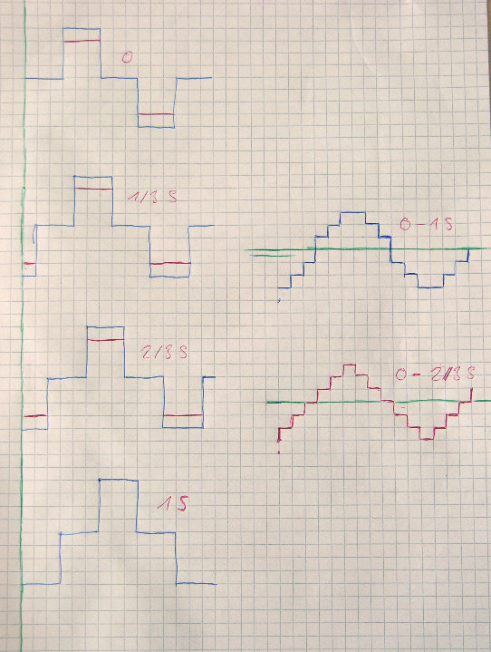
* This one schematic ( I can not find the link, it was japanese, 2 pictures ) shows original + 1/4 sample + 1/2 sample + 3/4 sample delay give a staircase.
But while playing around with possibilities, I found that original + 1/3 sample + 2/3 sample + 1 sample delay looks more like a sine.
* This one schematic ( I can not find the link, it was japanese, 2 pictures ) shows original + 1/4 sample + 1/2 sample + 3/4 sample delay give a staircase.
But while playing around with possibilities, I found that original + 1/3 sample + 2/3 sample + 1 sample delay looks more like a sine.
Bernhard said:
* Why is hardware os better working with SAA7220 in front ?
Linear interpolation such as that shown in the schematic assumes each point is joined by as straight line. That may well be a reasonable assumption at 100hz where you have 441 samples per cycle or even at 1KHz but not at 10Khz where you only have around 4 cycles. The SAA7220 provides more samples by increasing the effective sample rate by 4. Depending on the model, Wadia preceded the linear interpolation by a DSP based oversampling filter up to ,IIRC, 32Fs and Philips achieve 256Fs oversampling in Bitstream by combining a 16x FIR filter with 16x linear interpolation.
Hi,
I thought the linear interpolation in the saa7220 was only used when an error was detected.
Well that's what the datasheet seems to refer to the purpose of interpolation.
If your right though it explains alot (atleast to me). When i did my satellite image processing course at college we always started from raw data values (calibrated to sensors), and never from bilinear or cubic convultion manipulated images. The bilinear filtered images often 'sharpened' the image but u hadto take into account that this was created by an equation applied to the surrounding pixels so the data structure was changed.
Kind regards,
Ashley.
ash_dac said:Hi,
I thought the linear interpolation in the saa7220 was only used when an error was detected.
Ashley.
The linear interpolation in question does not take place in the SAA7220P.
rfbrw said:
Linear interpolation such as that shown in the schematic assumes each point is joined by as straight line.
Thanks, I still do not understand what bad thing may happen if there is no os filter and I do not understand that sentence.
ash_dac said:Hi,
Thanks for the info.
I'm still weighing up the merits of ripping saa7220's out of my players vs leaving them in.
Kind regards,
Ashley.
Then we are heading in opposite directions. What is under discussion is about increasing the oversampling ratio.
Bernhard said:
Thanks, I still do not understand what bad thing may happen if there is no os filter
It may sound awful but nothing bad will happen. This is audio, nothing bad ever happens which is why we have umbongo dots and shaftme stones.
and I do not understand that sentence.
Consider a wave form that has been sampled such that the first sample point is at zero, the next at the positive peak, then zero again, then the negative peak and back to zero again. You now have a single cycle. What kind of wave is it?
rfbrw said:
It may sound awful but nothing bad will happen. This is audio, nothing bad ever happens which is why we have umbongo dots and shaftme stones.
Consider a wave form that has been sampled such that the first sample point is at zero, the next at the positive peak, then zero again, then the negative peak and back to zero again. You now have a single cycle. What kind of wave is it?
Awful is bad enough.
It is a kind of squarewave
Now to see what happens, I draw the picture on the left side:
Original wave , 1/3 sample delay, 2/3 samples delay, 1 sample delay.
All added together give something that looks already very much like a sine, ( right side upper blue curve ) weather this is desireable or not...
Phase shift is exactly 1/2 sample.
As it is proposed in sidewinder, but only 3 times: Original wave , 1/3 sample delay, 2/3 samples delay, right side lower red curve gives the expected triangle.
So still can not see the problem not to have os filter.
For all intents and purposes, it's sine... at a frequency of half nyquist.rfbrw said:Consider a wave form that has been sampled such that the first sample point is at zero, the next at the positive peak, then zero again, then the negative peak and back to zero again. You now have a single cycle. What kind of wave is it?
You could synchronously sample a triangle wave or a sine wave and get the same result, but a triangular wave would imply the presence of 3rd/5th/etc harmonics - these are lost during the sampling process since they're above nyquist.
gmarsh said:
For all intents and purposes, it's sine... at a frequency of half nyquist.
After filtering...
- Status
- This old topic is closed. If you want to reopen this topic, contact a moderator using the "Report Post" button.
- Home
- Source & Line
- Digital Source
- Why NON-OS?