gmarsh said:
In discrete time, before any D/A conversion or filtering, it's a sine wave.
Ok, ok,
") but if you put the scope probe between I/V stage and analog filter, it is a square
but if you put the scope probe between I/V stage and analog filter, it is a square bump
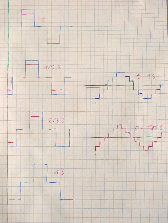
Now to see what happens, I draw the picture on the left side:
Original wave , 1/3 sample delay, 2/3 samples delay, 1 sample delay.
All added together give something that looks already very much like a sine, ( right side upper blue curve ) weather this is desireable or not...
Phase shift is exactly 1/2 sample.
As it is proposed in sidewinder, but only 3 times: Original wave , 1/3 sample delay, 2/3 samples delay, right side lower red curve gives the expected triangle.
So still can not see the problem not to have os filter.
Bernhard said:Ok, ok,
It's not strictly a square wave since it has zeros in it.
</semantics>But again in the digital domain, the information simply isn't there to tell you wether the original wave (before sampling) is a sine wave, modified square wave (which you're drawing), triangle wave, impulse train or whatever. It's safest to reproduce it as a sine.
gmarsh said:
It's not strictly a square wave since it has zeros in it.
But again in the digital domain, the information simply isn't there to tell you wether the original wave (before sampling) is a sine wave, modified square wave (which you're drawing), triangle wave, impulse train or whatever. It's safest to reproduce it as a sine.
Please note what I wrote: kind of squarewave
Of course it is very clear that it must have been a sine wave before sampling
Because the frequency we are talking about is on the upper end of the audio band and the bandwith of the audio band has already been limited by the microphone and other hardware stuff.
So the harmonics that would be necessary for everything else but a sine, like square or triangel can't exist
Bernhard,
It seems I am not explaining this too well so I'll change tack.
Overlay the five sample points I referred to earlier on a sine such that samples 1,3 & 5 are at zero, 2 is at the positive peak and 4 is at the negative peak. If you were to take the output of the SAA7220P or something similar the newly created sample points will fall ,near enough, on the line traced by the sampled wave and between the original sample points. This is because of all the digital trickery going on.
Now if you were to apply the same samples to a hardware oversampler as referred to earlier, the resulting samples would fall on a line drawn directly between the original samples as though the original wave was a triangle.
For a hardware oversampler to work well, there has to be enough samples such that if one were to overlay the sample points with the sampled wave and the join the dots, so to speak, the resulting wave would not differ significantly from the original.
Bernhard said:That sounds like the samples are unsure, so what is the difference if it is just unsure non os or unsure linear interpolated non os
Well I've tried to explain and I've clearly failed. Perhaps someone else can try.
Elso Kwak said:If you are not skilled in the game you should not try to change the rules.....
Confucius????
rfbrw said:
Confucius????
Haha, no our local artist referring to a Pope in that time.
- Status
- This old topic is closed. If you want to reopen this topic, contact a moderator using the "Report Post" button.
- Home
- Source & Line
- Digital Source
- Why NON-OS?