Also what if a driver rolls off and has no ringing, then does making it flat create a ring?
It cannot "roll off" without some ringing unless it is over-damped, and then making it flat will not create any ringing. If it is under-damped and hence does ring, then making it flat will remove the ringing.
It has been an in-depth discussion and over my head. But here's my intuitive take, which supports one of the sides of this debate:
a device, whether speaker box or acoustic guitar, with resonance(s) rings because the ringing gets stimulated in various ways and then colours the sound (to greater or lesser audible degree); you can't "unring" the device by controlling the input signal EQ, no matter what the simplified idealistic math model says.
B.
Last edited:
I appreciate some of the explanations on here.
Yea I know it does go against intuition somewhat. But since Geddes, Simon, Zaph all say the same thing I wouldn't be too quick to argue with it.
The key is a linear system, which a simple cone is for the most part. Something complex like a box is far from that. I don't think a flexible cone in break up is linear either but Idk, so we're talking about pistonic behavior here.
I still have a hard time believing that a simple tweeter can be eq'd to sound like a 500$ beryllium scanspeak. But there could be other issues that maybe create audible differences. I don't know if it would sound as "quick" which isn't necessarily a scientific term.
It has been an in-depth discussion and over my head. But here's my intuitive take, which supports one of the sides of this debate:
a device, whether speaker box or acoustic guitar, with resonance(s) rings because the ringing gets stimulated in various ways and then colours the sound (to greater or lesser audible degree); you can't "unring" the device by controlling the input signal EQ, no matter what the simplified idealistic math model says.
B.
Yea I know it does go against intuition somewhat. But since Geddes, Simon, Zaph all say the same thing I wouldn't be too quick to argue with it.
The key is a linear system, which a simple cone is for the most part. Something complex like a box is far from that. I don't think a flexible cone in break up is linear either but Idk, so we're talking about pistonic behavior here.
I still have a hard time believing that a simple tweeter can be eq'd to sound like a 500$ beryllium scanspeak. But there could be other issues that maybe create audible differences. I don't know if it would sound as "quick" which isn't necessarily a scientific term.
Last edited:
I don't see why not, theoretically if you could identify each of the resonances accurately, then use filters with the same properties to cancel them. As said previously, linearity is assumed, so it's not going to be perfecta device, whether speaker box or acoustic guitar, with resonance(s) rings because the ringing gets stimulated in various ways and then colours the sound (to greater or lesser audible degree); you can't "unring" the device by controlling the input signal EQ, no matter what the simplified idealistic math model says.
Other distortions would still be present, perhaps EQing out some of the resonances would reduce them to a degree?I still have a hard time believing that a simple tweeter can be eq'd to sound like a 500$ beryllium scanspeak. But there could be other issues that maybe create audible differences. I don't know if it would sound as "quick" which isn't necessarily a scientific term.
Don't take my word for it, take some measurements of your own.Once the cone is ringing, I would not consider it minimum phase. As a matter of fact, it cannot be minimum phase if there is a breakup mode (normally called first bending mode in general engineering terms) because clearly the inner and outer parts of of the cone are not in phase with each other.
Measure any random conventional single cone driver you have sitting around (woofer, mid, full range, doesn't matter) that has known cone breakup resonances, even severe ones.
Have a look at the excess phase and excess group delay, and compare them to phase and group delay. What do you see ?
I've done this on many drivers, and I haven't found one yet where the resonances aren't completely minimum phase. Yes even on a whizzer cone full range driver, surprisingly.
On a single cone driver what I invariably find is that within a small margin of error there is no excess phase and the excess group delay response is a flat line which only curves up a bit at the bottom end due to limited gate time of the measurement causing errors in the low frequency phase estimation.
If you look at group delay you see the group delay variations at cone resonances that result from the rapid phase shifts but excess group delay is a near flat line with no trace of any of the resonances.
On a dual cone whizzer cone driver what you do see is some excess group delay and phase - but not at the cone resonances - just a very smooth, broad shift that looks not surprisingly like the excess group delay of a two way speaker with a 12dB/oct crossover.
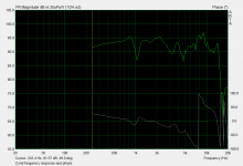
Here is an example for you, and I've actually taken the more challenging example of a large dual cone full range driver to show that even in this situation the cone resonances are still minimum phase despite the extremely high modal density that must be present on the cone at high frequencies for an 8" driver... First the amplitude and (measured) phase response.
Plenty of peaks and dips there - must be resonances right ?
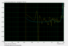
Here is the group delay (yellow) overlaid on top of the excess group delay: (blue)
I think this is very cool - in the group delay you can clearly see the group delay reflecting the resonances shown in the amplitude and phase response - the surround dip at 1Khz is especially obvious, but in the excess group delay (which is just group delay of excess phase) there is absolutely zero trace of any of these resonances at all. I think that's quite profound and it certainly shocked me when I first discovered this years ago.
All you see is a gradual hump at around 6Khz which is a result of the fact that the two cones have an mechanical/acoustic crossover at about 6Khz, so like any other crossover you see a peak in the excess group delay near the crossover frequency.
(This excess group delay measurement is in fact how I know what the crossover frequency between the two cones is, and this could be used to measure the acoustic/mechanical crossover frequency of any whizzer cone driver...and incidently, its interesting to note that the excess group delay minimum at 10Khz exactly matches the excess group delay minimum near 1Khz - which shows that the two cones are properly time aligned - which is not the case on some dual cone drivers I have measured)
If I were to repeat this same measurement on a single cone driver (which I have) you'd find the excess group delay is basically flat through the majority of the drivers bandwidth, with it just curving up at both ends due to measurement error. I used the dual cone driver as an example as otherwise I'd just have a boring, flat line...
So at least in this measurement there is proof that all the cone resonances are minimum phase as they don't show up even slightly in the excess group delay response. Which also means that even though the driver as a whole is not minimum phase, because the resonances are they can still be corrected by standard individual minimum phase PEQ or RLC notches, as I'm doing in my crossover.
Of course - I'm not suggesting that all drivers are minimum phase - clearly there are some that are not - like the one I just posted above. And you should always measure it to find out if it is the case or not.Under some studies, it is possible to assume minimum phase, but in the process of perfecting a device, one cannot assume such, but rather best look at the actual physical dynamics which is where the Klippel scanner is very useful.
But I'd say in the majority cases, the resonances of all cone drivers are minimum phase. I'm yet to find an exception to that rule, and on the face of it that does seem surprising, but the measurements are hard to dispute.
Attachments
Last edited:
Soo if I EQ a diaphragms resonance so that I get a flat FR.....
1- if the diaphragms mechanical properties are linear spring in nature and very low hysteresis then I should have little to no audible coloration ?
2- if the diaphragms mechanical properties have enough hysteresis which I believe can result in non linear properties? then even IF I EQ to flat I may have some audible coloration?
Is the above true? And if it is, is it noticeable because of the non linear property of the materials flex character OR is it noticeable because such a property usually results in a resonance that is lower in Q BUT often spread out over a long enough range the ear to more easily pick up on it?
I don't see why not, theoretically if you could identify each of the resonances accurately, then use filters with the same properties to cancel them. As said previously, linearity is assumed, so it's not going to be perfect
One difference is that resonances take time to build to their full strength. So when a tone starts at the input, it will take a few cycles (depending on res, ~5 to dozens?) for the resonance to build and level off.
If you decrease the input to compensate for the resonance then you're creating an initial ramp in the tone as it builds to resonance.
In a system with no resonance to start with, the output will more match the input with less of this initial ramping.
The key is whether we hear this. Gedlee's research has shown that we hear bass over time so these initial conditions don't matter. I'm not sure how much it affects our higher hearing (over ~ 200 Hz, where sound changes from modal to direction in most home rooms?). Hopefully someone will chime in.
Cheers,
Jeff
PS I hope I got all that right

Last edited:
Soo if I EQ a diaphragms resonance so that I get a flat FR...
Answer: Yes,
Look at the Tale of two Towers thread by member Wesayso. 25 full range Vifa drivers per side, properly equalized. The result, both in measurements and sonically, is nothing short of spectacular. I have auditioned these speakers and so have a number of other DiyAudio members. Also, member RA7 in the USA built a similar speaker. His local Hi End Audio Group was astonished by the results. 9 bucks per driver and no-one is ever craving again for Beryllium domes.
A conceptually very different speaker was designed by member Barleywater, who also achieved outstanding results by equalizing.
Soo if I EQ a diaphragms resonance so that I get a flat FR...
Answer: Yes,
Look at the Tale of two Towers thread by member Wesayso. 25 full range Vifa drivers per side, properly equalized. The result, both in measurements and sonically, is nothing short of spectacular. I have auditioned these speakers and so have a number of other DiyAudio members. Also, member RA7 in the USA built a similar speaker. His local Hi End Audio Group was astonished by the results. 9 bucks per driver and no-one is ever craving again for Beryllium domes.
A conceptually very different speaker was designed by member Barleywater, who also achieved outstanding results by equalizing.
but what about #2?
This is not really correct.One difference is that resonances take time to build to their full strength. So when a tone starts at the input, it will take a few cycles (depending on res, ~5 to dozens?) for the resonance to build and level off.
If you decrease the input to compensate for the resonance then you're creating an initial ramp in the tone as it builds to resonance.
In a system with no resonance to start with, the output will more match the input with less of this initial ramping.
A notch with the same centre frequency and Q, and an attenuation that matches the gain of the original resonance will have the exact same response in the time domain, but the phase will be reversed.
When the two are summed together you get a net zero result with no ringing. That's all that's really needed to understand it.
Once the resonance is cancelled out the slow buildup you speak of no longer exists.
A signal in this frequency range can pass through the system unaltered with whatever modulation rate it originally had, uninfluenced by either the peak or notch as they are cancelling each other out.
It's not that hard to test either, if you have two accurate PEQ's. Pass a test signal from something like ARTA though one of them with say a 1Khz, +6dB 1/3rd octave peak, measure the output - look at the frequency response, phase response and CSD - see all the telltale signs of a resonance.
Pass that modified signal into another PEQ (perhaps the other stereo channel of the same unit if you're stingy and it allows you to operate in a double mono mode with different filters for each channel) which is set to 1Khz, -6dB, 1/3rd octave notch, and measure the output of that, and you'll find.....no trace of the resonance, if the correction was accurate.
Flat frequency and phase response, and nothing on the CSD. Try playing around with the centre freqeuency, bandwidth/Q and gain of one of the PEQ's to cause a deliberate mismatch and see what that does to each measurement, and particularly to the CSD. I've done this before and it is quite interesting.
Soo if I EQ a diaphragms resonance so that I get a flat FR.....
1- if the diaphragms mechanical properties are linear spring in nature and very low hysteresis then I should have little to no audible coloration ?
2- if the diaphragms mechanical properties have enough hysteresis which I believe can result in non linear properties? then even IF I EQ to flat I may have some audible coloration?
Is the above true? And if it is, is it noticeable because of the non linear property of the materials flex character OR is it noticeable because such a property usually results in a resonance that is lower in Q BUT often spread out over a long enough range the ear to more easily pick up on it?
All of these questions depend on "audible" as a premise and that would have to be tested scientifically, which has never been done. Hence there cannot be a definitive answer to any of them. But I would say that 1) is likely true as well as 2), except that 2 is unlikely to occur in practice to the extent that its coloration would be significant. Most material flex is linear, so your last point is again not likely to occur either.
This is not really correct.
A notch with the same centre frequency and Q, and an attenuation that matches the gain of the original resonance will have the exact same response in the time domain, but the phase will be reversed.
When the two are summed together you get a net zero result with no ringing. That's all that's really needed to understand it.
Once the resonance is cancelled out the slow buildup you speak of no longer exists.
A signal in this frequency range can pass through the system unaltered with whatever modulation rate it originally had, uninfluenced by either the peak or notch as they are cancelling each other out.
It's not that hard to test either, if you have two accurate PEQ's. Pass a test signal from something like ARTA though one of them with say a 1Khz, +6dB 1/3rd octave peak, measure the output - look at the frequency response, phase response and CSD - see all the telltale signs of a resonance.
Pass that modified signal into another PEQ (perhaps the other stereo channel of the same unit if you're stingy and it allows you to operate in a double mono mode with different filters for each channel) which is set to 1Khz, -6dB, 1/3rd octave notch, and measure the output of that, and you'll find.....no trace of the resonance, if the correction was accurate.
Flat frequency and phase response, and nothing on the CSD. Try playing around with the centre freqeuency, bandwidth/Q and gain of one of the PEQ's to cause a deliberate mismatch and see what that does to each measurement, and particularly to the CSD. I've done this before and it is quite interesting.
Right. The above is easy to understand and prove.
My quarrel is when we get into the physical world with devices or systems with “energy persistence” or devices or systems that disperse energy over time. It seems like these devices and systems are being included in the “you can eq it all away” camp.
Barry.
My quarrel is when we get into the physical world with devices or systems with “energy persistence” or devices or systems that disperse energy over time. It seems like these devices and systems are being included in the “you can eq it all away” camp.
Barry.
But that's not a quarrel that you can win because it's wrong. This idea of "energy persistence" is simply incorrect.
Any way you look at it, a driver running at low power will have less distortion than a driver running at high power.
While keeping an eye on other compromises (cone break-up, cabinet size etc), larger more efficient speakers will have less distortion than, say, a 4" driver moving 10mm p/p absorbing 100w+.
That said, high-efficiency PA speakers have a wide range of performance. I'd take a low-efficiency 7" midbass with lots of copper in the motor and a really nice cone/suspension over a high-efficiency cheap 10" PA driver. An expensive PA driver will likely have less distortion than either for a given power input.
Chris
+1
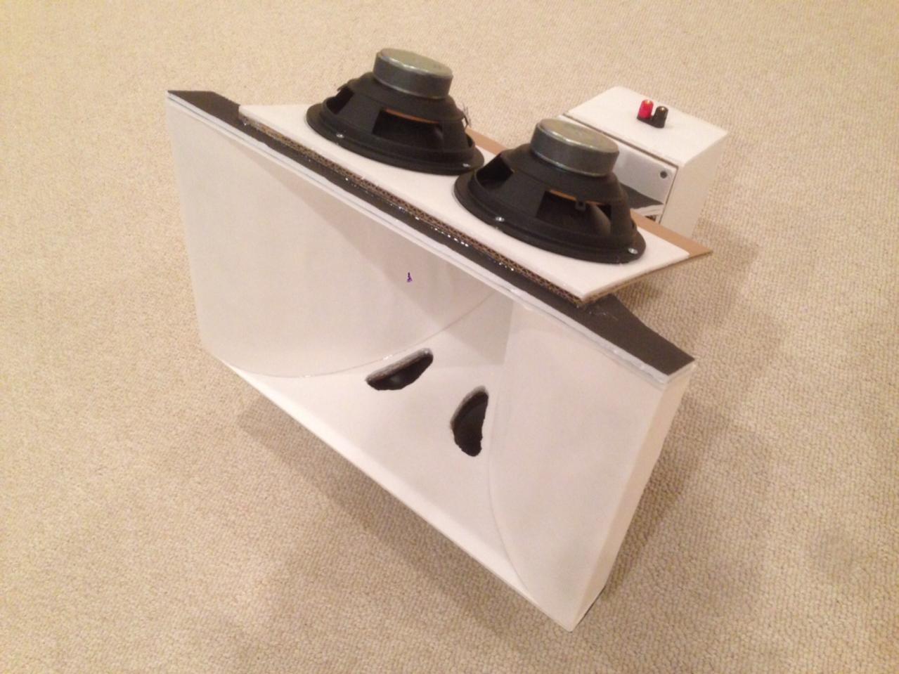
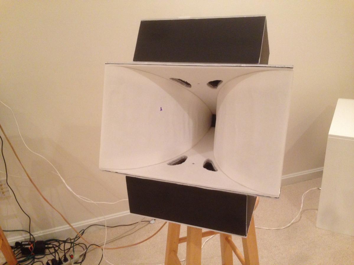
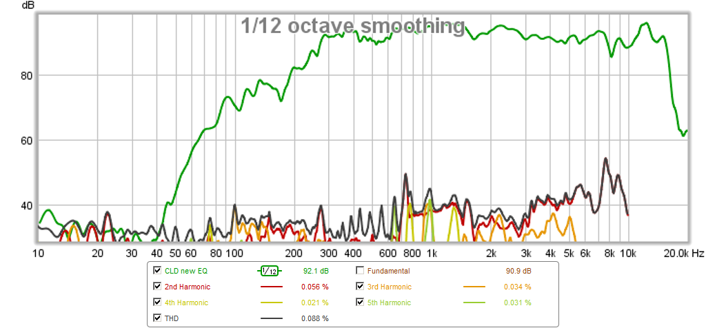
I took a common run of the mill $12 TC9FD and put it behind a tractrix horn to boost the sensitivity. It turns out that the horn does such a good job coupling the driver to the air column that simulations show only a 40micron cone movement was enough to make 100dB at 1m. When you hear this, the sound is so clear, it is stunning. It sounds so much cleaner than any CD at the same SPL. It is easy to accidentally play at 115dB and not know how loud it is until you turn it off and your ears ring. So reduction of cone motion is everything.
And this was a quick and dirty foam core horn too.
Presenting the Trynergy - a full range tractrix synergy.
I did a similar thing with the PRV 5MR450NDY and it sounded even cleaner and was louder:
Last edited:
"Most material flex is linear"
Hmm yea but isnt the whole reason we may apply a "damping" material of some sort because of its time delay between stress and strain ie; hysteresis? and isnt that property non linear ?
Or is it that this effect is simply very small until we grossly distort the diaphragm?
Hmm yea but isnt the whole reason we may apply a "damping" material of some sort because of its time delay between stress and strain ie; hysteresis? and isnt that property non linear ?
Or is it that this effect is simply very small until we grossly distort the diaphragm?
Last edited:
There is no fundamental difference between a mechanical resonance and an electrical resonance.My quarrel is when we get into the physical world with devices or systems with “energy persistence” or devices or systems that disperse energy over time. It seems like these devices and systems are being included in the “you can eq it all away” camp.
If you have a weight (mainly the cone) attached to a spring (spider and surround) and something that also looses energy through friction (also the spider and surround, mainly) then you have a mechanical resonance with a defined centre frequency, Q and amplitude.
Energy transfers back and forth between kinetic energy (maximum at maximum velocity) and potential energy in the spring (maximum at zero velocity) with some loss as that happens.
Now consider an electrical resonator formed by a coil, capacitor and resistor. Now you have energy travelling back and forth between an electrostatic field in the capacitor and a magnetic field in the coil, with some energy being lost in the resistance along the way.
It also has a centre frequency, a Q and an amplitude. It follows the same amplitude vs phase relationship as the mechanical resonance.
So how is it different ?
Cone breakup resonances look more complicated than a simple mass spring resonance like the fundamental bass resonance at first, but if they measure minimum phase (which I just showed in my example measurements) then they must abide by the same rules.
There are two complications with cone breakup resonances - the first is that the driver response isn't the same on all axes, and the higher into the modal breakup range of the cone you go the more complex things get off axis. So any correction of those higher modes would only be right at one point in space.
This places an upper frequency limit on how high you can realistically EQ resonances of a driver relative to the size of the driver and the order of the modes forming on the cone.
So I can successfully EQ a 4Khz peak on my 8" Coral drivers and that notch is "close enough" over a fairly wide range of angles, but I would not be able to EQ a 15Khz resonance without it being completely wrong on a different axis due to the size of the driver.
The second is that the resulting frequency response even at one point in space can be very complicated and detailed looking consisting of a lot of individual resonances all added together to give the ragged response you often see.
But if you wanted to spend the time you could analyze the response to pinpoint each and every one of those resonances, what their centre frequencies, Q's and gains were, and I'm sure there is software somewhere that would do that, and you could manually do it with a CSD.
There might be a dozen or more discrete resonances on a poor driver that add up to give that mountain range frequency response, and probably most of them are very high Q.
This is why in practice I try to tackle the resonances mechanically first, and with the right techniques you can reduce the problem to just 2 or 3 discrete relatively low Q resonances that you can successfully EQ instead of a large number of unstable high Q resonances that are practically speaking not feasible to EQ with discrete notches, and certainly not passively.
To EQ a driver resonance successfully it needs to:
1) Be minimum phase - check.
2) Be much the same over the angular listening window of the speaker - which depends on how high order the mode is and whether its really a resonance or whether it is actually a diffraction artefact. To find out, do a set of frequency response measurements from 0 out to about 45 degrees - if the peak stays relatively stable its a mechanical resonance. If it comes and goes at different angles or only exists at certain angles its probably diffraction!
3) Be low enough Q so that the resonance is mechanically "stable" and doesn't drift around with changes in humidity, temperature, vibration etc and that the tuning of the notch filter doesn't become impossibly critical.
FIR convolvers can theoretically correct "anything" at a single point in space no matter how bad, but you still have the issue of it being wrong at other listening angles, or the possibility that high Q driver resonances are not stable and thus the correction may be wrong from one day to another.
I've already seen evidence of high frequency resonances drifting over time on paper cones since the moisture content of the paper affects the damping characteristic of some cone resonances! Thus they can sound a bit different in dry vs humid conditions if the paper doesn't have any additional damping.
This is another reason I think the damping foam strips I use work well - they become the "dominant" damping control of the cone in those higher breakup regions which makes the performance of the driver more stable with environmental changes than it was when there was just paper where the changes in the properties of the paper had a larger effect on the response of the driver.
Ideally you would seal the paper from the environment with a moisture proof coating (sometimes done) or use a material that is non hygroscopic, but both tend to result in heavier cones.
Last edited:
- Home
- Loudspeakers
- Multi-Way
- Who makes the lowest distortion speaker drivers