Brit01,
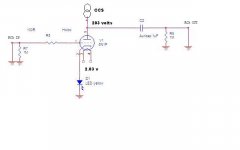
I'm a bit confused, you mention 2.03V across a yellow LED for cathode bias, but that has no direct bearing on the CCS current. It will affect plate voltage at whatever current the CCS is set for. The 120R resistor in the CCS will set the CCS current. Measure three things: 1) the exact value of the resistor, could be a few ohms off of 120; 2) the voltage across the 120R nominal resistor; 3) the voltage from plate to ground. Do this for each plate in question. SS devices have even bigger variations than tubes; both CCS will probably be different.
Armed with the above information, Ohm's law will give you the CCS current. Voltage across the 120R resistor, divided by the actual resistor value. That will be the actual plate and CCS current.
Next look at the plate voltage under these conditions. Look at the 6N1P plate curves to determine where you are. TubeCad can also fill you in, if you input 6N1P data.
The question that needs to be answered is how much voltage, peak to peak, does your output tube require for maximum, undistorted output? Look at output stage gain and how much output voltage you need to create.
If you have a signal generator, multimeter and scope, you can determine the voltage needed by driving the output tube's grid (through a coupling cap of course) to clipping on the scope, connected to the speaker terminals, while measuring the signal generator's output at that point. A load, representative of your speaker must be connected to the amp's output terminals. This is typically a non-inductive high wattage resistor of 8 ohms. That drive voltage value is very important. Your meter will measure the RMS value, multiply by 1.414 to get the peak value of signal drive voltage needed.
Your driver tube's B+ supply must be greater than the idle plate voltage, plus the peak (not peak to peak) drive voltage, plus the minimum voltage drop across the CCS. To this number, I'd want to add several volts of cushion.
For instance, if you determine that your output tube needs 10V RMS to achieve clipping, then the peak value of the drive needs to be 14.14 volts.
If your 6N1P has a raw B+ of 208 volts and your plate voltage is 150 volts with 15mA through the current source, then 58 volts is available to drive the output tube in one direction (peak). In the other direction, the tube would conduct more and the plate voltage would drop by 58 volts. now the CCS will require a few (maybe 5 or so) volts to operate, bare minimum. Keeping away from bare minimums, it would be possible for this setup to deliver 48 volts or so, linearly. This would be way more than the output tube needs and so most distortion should take place in the output tube, as it should be.
Now, let's assume that you actually have 200 volts on the plate and 208 volts, raw, into your CCS. Since the CCS will need at least 5 volts or so to operate, any greater drive signal than 3 volts (6 volts peak-to-peak) to the output tube will result in severe distortion.
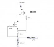
If your CCS is operating at other than desired current, you'll have to change the 120R resistors. (That's why I use a nice Bourns or Vishay 1k 10+ turn Cermet trimpot here). To lower your plate voltage (and gain headroom to avoid clipping) you'll need to change the LED bias to a voltage which will cause the tube to conduct more. That would be a lower voltage.
[I'd come up with the numbers for you right now, but I've recently switched to an ubuntu system and can't run TubeCad on it, even in a Wine layer].
I know this was long-winded, but I hope it helps your understanding.
On the subject of series resistance in the power supply, I disagree (respectfully) with Gordy. There are no perfect resistors, and they do have a sound, even in a power supply. Pick a sensitive spot in your system and experiment with metal films, carbon films, carbon comps, wirewounds and bulk foils. Make sure they are the same value, and see if you don't hear a difference. If you don't then let it be.
In power supplies, many members of our DIY club have experimented with differing values and types of resistors. It does seem that the universal outcome is that the smallest value resistor seems to lead to the best sound. Of course many variables need to be balanced to make the change, but it's not just me with this observation. That's why I suggested that you experiment and reach your own conclusions, once you have the CCS design nailed down. If you don't hear a difference, that's cool, you're done.
Stuart
I'm a bit confused, you mention 2.03V across a yellow LED for cathode bias, but that has no direct bearing on the CCS current. It will affect plate voltage at whatever current the CCS is set for. The 120R resistor in the CCS will set the CCS current. Measure three things: 1) the exact value of the resistor, could be a few ohms off of 120; 2) the voltage across the 120R nominal resistor; 3) the voltage from plate to ground. Do this for each plate in question. SS devices have even bigger variations than tubes; both CCS will probably be different.
Armed with the above information, Ohm's law will give you the CCS current. Voltage across the 120R resistor, divided by the actual resistor value. That will be the actual plate and CCS current.
Next look at the plate voltage under these conditions. Look at the 6N1P plate curves to determine where you are. TubeCad can also fill you in, if you input 6N1P data.
The question that needs to be answered is how much voltage, peak to peak, does your output tube require for maximum, undistorted output? Look at output stage gain and how much output voltage you need to create.
If you have a signal generator, multimeter and scope, you can determine the voltage needed by driving the output tube's grid (through a coupling cap of course) to clipping on the scope, connected to the speaker terminals, while measuring the signal generator's output at that point. A load, representative of your speaker must be connected to the amp's output terminals. This is typically a non-inductive high wattage resistor of 8 ohms. That drive voltage value is very important. Your meter will measure the RMS value, multiply by 1.414 to get the peak value of signal drive voltage needed.
Your driver tube's B+ supply must be greater than the idle plate voltage, plus the peak (not peak to peak) drive voltage, plus the minimum voltage drop across the CCS. To this number, I'd want to add several volts of cushion.
For instance, if you determine that your output tube needs 10V RMS to achieve clipping, then the peak value of the drive needs to be 14.14 volts.
If your 6N1P has a raw B+ of 208 volts and your plate voltage is 150 volts with 15mA through the current source, then 58 volts is available to drive the output tube in one direction (peak). In the other direction, the tube would conduct more and the plate voltage would drop by 58 volts. now the CCS will require a few (maybe 5 or so) volts to operate, bare minimum. Keeping away from bare minimums, it would be possible for this setup to deliver 48 volts or so, linearly. This would be way more than the output tube needs and so most distortion should take place in the output tube, as it should be.
Now, let's assume that you actually have 200 volts on the plate and 208 volts, raw, into your CCS. Since the CCS will need at least 5 volts or so to operate, any greater drive signal than 3 volts (6 volts peak-to-peak) to the output tube will result in severe distortion.
If your CCS is operating at other than desired current, you'll have to change the 120R resistors. (That's why I use a nice Bourns or Vishay 1k 10+ turn Cermet trimpot here). To lower your plate voltage (and gain headroom to avoid clipping) you'll need to change the LED bias to a voltage which will cause the tube to conduct more. That would be a lower voltage.
[I'd come up with the numbers for you right now, but I've recently switched to an ubuntu system and can't run TubeCad on it, even in a Wine layer].
I know this was long-winded, but I hope it helps your understanding.
On the subject of series resistance in the power supply, I disagree (respectfully) with Gordy. There are no perfect resistors, and they do have a sound, even in a power supply. Pick a sensitive spot in your system and experiment with metal films, carbon films, carbon comps, wirewounds and bulk foils. Make sure they are the same value, and see if you don't hear a difference. If you don't then let it be.
In power supplies, many members of our DIY club have experimented with differing values and types of resistors. It does seem that the universal outcome is that the smallest value resistor seems to lead to the best sound. Of course many variables need to be balanced to make the change, but it's not just me with this observation. That's why I suggested that you experiment and reach your own conclusions, once you have the CCS design nailed down. If you don't hear a difference, that's cool, you're done.
Stuart
Just saw that 208V/203V setup. That's the problem. If you want 203 volts across the tube (and at 15mA that's 3 watts per plate!!!) then raise B+. I'd be inclined to lower the plate voltage by deceasing the cathode bias voltage. Arrange for signal swing per my previous post.
Don't know what cathode voltage you need? Pot to the rescue. Replace the LED with a linear 1k pot and adjust until you get the plate voltage you want at the current you want. Current is still set in the CCS, first!)
Stuart
Don't know what cathode voltage you need? Pot to the rescue. Replace the LED with a linear 1k pot and adjust until you get the plate voltage you want at the current you want. Current is still set in the CCS, first!)
Stuart
Brit01, your figures (about 2V cathode and about 200V anode) intersect at about 18mA on the curves as shown in the 6N1P datasheet. That is about 3.6W, which is above the 2.2W limit of the anode. Turn it off, and then follow sepolansky's advice...
Remember that you are going to get a gain of about 30-35-ish with that tube. So 1 volt in and 35 out!
From the datasheet curves it looks OK at about 8mA, -2 V bias, about 150V anode.
Remember that you are going to get a gain of about 30-35-ish with that tube. So 1 volt in and 35 out!
From the datasheet curves it looks OK at about 8mA, -2 V bias, about 150V anode.
Brit01,
On the subject of series resistance in the power supply, I disagree (respectfully) with Gordy.
Disagreement is fine. Have a good weekend
")
Raw voltage (before CCS): 199 v
...and what is it after the CCS, directly at the anode?
sorry it is 195v. getting about 4 v difference.
I'd like to try and stick with the led bias as I've had good results.
Now I just tried a 6N6P at a plate voltage of 103 v and B+ of 138v.
current across CCS was 16mA. The DN2540's were getting hot with this.
voltage across 120ohms was 1.98 v.
I'd like to try and stick with the led bias as I've had good results.
Now I just tried a 6N6P at a plate voltage of 103 v and B+ of 138v.
current across CCS was 16mA. The DN2540's were getting hot with this.
voltage across 120ohms was 1.98 v.
Last edited:
Brit01,
Okay, so current at 10.4mA is just fine. You need to lower your plate voltage per Gordy, to 150V or so. Try a red LED (~1.7V) and see what you get. An IR LED should get you 1.2V, that may be too low, but worth a shot.
But, you really need to figure out what you're asking your driver to do, then adjust accordingly.
Stuart
tried a different type yellow led with lower voltage, 1.85v.
Didn't make any difference to the plate voltage.
unfortunately I don't have any 1.7v red leds at the moment.
So I can try resistor bias
or
go with a different tube such as the 6N6P at at plate voltage of around 100V maybe.
update: tried with lowering resistor bias down to 120 ohms. Plate Voltage only dropped a few volts with bias at 1.5v.
What effect would increasing the CCS resistor bias have on the plate vooltage?
time to hit the sack, its 1.30am here. and my wife is due to give birth in a few days!
Hope I can get this SS CCS up and running before then.
Otherwise I'll go back to my pentode CCS which I had great results from.
Last edited:
From the datasheet curves...
Just realised that for 6N1P I have an old (generic Russian) and a new-ish (Svetlana) datasheet, and the two curves are different! Damn.
So 6N6P? I've no personal experience with it, but glancing at a generic datasheet it looks nice. Your 103 V and 16 mA lines up with about -2.5V bias, and it's well within the dissipation of the tube. Looks quite good on paper. Apparently the gain is about 20-ish.
With 35 V across the CCS, 16mA current, about -2.5V bias, and about 100 V on the plate you should get an output swing above + / - 20V. Should be quite undistorted into a high R load.
sorry it is 195v. getting about 4 v difference.
There's the problem right there. Decrease cathode bias, reduce set current (change 120R to 200R to start), or increase available B+. You want at least 20-30V across the CCS for a stage that will swing a couple of volts. Easiest check that this is the right path is to change the 120R resistor.
pchw, yes, that works great for a tail.
I put 220 ohms on the CCS bias. (couldn't find a 200).
Now I've got better results with the 6N1P.
Plate V: ~170v
B+: 225 v
current across CCS (2/220): 9.1 mA. Not going to burn out the 1w DN2540 with this no?
Do these figures look reasonable?
Thanks very much guys.
Update: music test sounds superb now. no distortion, just sweet tunes.
BUT the dn2540s are getting damn hot, almost too hot too tough. I switched it off as I think they will burn out.
I think I willl switch back to my pentode CCS until I get some 15 watt DN2540s.
Last edited:
- Status
- This old topic is closed. If you want to reopen this topic, contact a moderator using the "Report Post" button.
- Home
- Amplifiers
- Tubes / Valves
- Which SS CCS for the plate load on a 6N1P?