
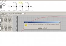
trying to simulate a smaller B+ with PSUII but it keeps showing an error "current sink has pulled voltage below zero volts".
I only have a 275 volts tranny and I'm trying a new SS rectifier with FREDs.
Can't get the B+ low enough for my small 6N1p and this CCS.
Any suggestions on the design? (apart from going back to my valve rectifier or using chokes)
Maybe a voltage divider?
Last edited:
6X4. Indirectly heated, connect to your 6N1P filament supply
sorry Stuart but I want to use a SS rectifier with some new FREDs I have but B+ is just too high.
Would a voltage divider work to reduce the B+ with some beefy resistors?
maybe 2000 ohms and 4000 ohms ratio (with 25mA flowing). I have some 20 watts. Although 25mA will create about 4 watts I think.
so I'd get ~150V from 300V.
Last edited:
Brit01,
Don't like series resistance in power supplies. Seems to never sound as good as without the series resistance. Another current source upstream, for both channels could work well. I like using a source a friend designed (I'm not sure that I'm allowed to share, I'll have to ask) loosely based on the C4S. Allegedly Pimm's best variation, the one where LND150s are included for the voltage reference current works very well. Using one of those and a shunt reg (could be a VR tube or two) works very, very well. The VR tubes require no shunt cap and no filament supply, so the space you lose for the shunt tubes, you gain in leaving out the P/S caps.
This is a bit complicated, but I'd go through it to avoid series resistance in the B+. If you must use resistance, please, no cement resistors. They sound dreadful.
Maybe, if you add resistance on the AC side of things, ahead of the FREDs, it wouldn't be as bad. Never tried myself, but others say good things.......
Stuart
Thanks for the ideas Stuart.
Maybe you're right about the series resistors.
Whole idea of the CCS is for improvements and I could be taking a step back with the voltage divider.
Think I have some options that are simple.
Buy a new 220/110 reducer transfomer to use with the FREDS. Cheap and easily available here.
Or go back to my 6X5 rectifier already up and running and use this with the CCS.
Shame I didn't pick up the 15watt DN2540's while I was away in USA. My error.
or also try the resistors on the AC side.
Last edited:
Thinking of how to simulate a resistor on the AC side I can increase the resistance of the transformer on PSUII.
My tranny is 275 V ,52 ohms. If I increase this to 2000 ohms simulating a resistor before the rectifiers would this work?
If simulate ok and brings the voltage way down to a good level.
I can get 220 B+ with 450ohms/480uf/450ohms/680uf.
My tranny is 275 V ,52 ohms. If I increase this to 2000 ohms simulating a resistor before the rectifiers would this work?
If simulate ok and brings the voltage way down to a good level.
I can get 220 B+ with 450ohms/480uf/450ohms/680uf.
Maybe you're right about the series resistors.
Consider this: no need to mess with the transformer resistance in the simulation. Instead just bang resistors in front of your smoothing capacitors. Make RCRC (or RCRCRC, etc.) and your voltage can be dropped right down.
The resistors (especially the first one) will get hotter than a quick calculation might suggest, but that's what high-dissipation alluminium bodied resistors are made for!
The extra resistance in the supply does not have a 'sound quality', it has resistance. However that resistance will be low compared with the very high resistance of the CCS, so there should be no issues.
If your voltage is still too high consider a current limiter before the transformer in the AC line. They drop some voltage and usually get quite hot.
Just a thought. Enjoy ya weekend.
Hi Gordy
That was my first intention to drop high resistors , RCRCRC etc but the simulation with PSUII kept giving me the zero voltage warning which concerned me.
So I can add RC series until I get the low voltage I need without any consequences to the diodes or tranny even though the PSUII warms me?
I know its a different story with the rectifier tubes which have a limit.
Solid state diodes have a limit too, but normally you can buy chunky items that are very tough. I used 600V Schottky diodes. Farnell part number 1300073 according to my notebook. (I think they are rated at about 15A, maybe 17A, can't remember).
However PSUDII seems accurate normally, so without seeing your sim it's difficult to say.
However PSUDII seems accurate normally, so without seeing your sim it's difficult to say.
trying to simulate a smaller B+ with PSUII but it keeps showing an error "current sink has pulled voltage below zero volts".
I only have a 275 volts tranny and I'm trying a new SS rectifier with FREDs.
Can't get the B+ low enough for my small 6N1p and this CCS.
Any suggestions on the design? (apart from going back to my valve rectifier or using chokes)
Maybe a voltage divider?
You're doing something wrong. Can you show a screenshot?
FWIW, with a 15mA CC load, a FW solid state bridge, and a 275 transformer, I used a CRC filter, 47u - 1k - 220u and got a fine result; 367V B+, less than 12mV p-p ripple.
edit: at 30 mA, I get 350V, no error message. You're trying to get much too fancy and complex. KISS.
screenshot displayed above SY
I tried with CRCRC and CRCRCRC
Too much value in the capacitors. The transformer and bridge just can't charge them initially, hence the error message.
Try CRCRC with all 3 C's at 47uF and 470 resistors as a starting point. You should get B+ around 260v and very low ripple at 30mA load. They will charge to full B+ in less than 1 second, so cut your reporting time back to 5s.
I'm a noob at PSUD as well, but I have just done a PS for a 6N1P (as part of a PP EL84 amp), so this lot is fresh in my mind.
Hope that helps
Gary
Last edited:
Hello Brit01, I don't know about your Mosfet, but I think that 1uF cap is not doing too much for you. You might want to try upping it to 100uF (and then you can buy three the same!).
Your 5k resistor is going to be dissipating a lot of heat... about 4.5W of hotness. Consider running three high power 15K in parallel, bolted to metal. (Possibly RS part 683-5975 ?).
Regards,
J.
Your 5k resistor is going to be dissipating a lot of heat... about 4.5W of hotness. Consider running three high power 15K in parallel, bolted to metal. (Possibly RS part 683-5975 ?).
Regards,
J.
Hi guys,
success so far with no heat or smoke.
I've got a cascode DN2540 for each plate of the 6N1P. So 4 DN2540's in total. 2 for each plate load.
The psu consists of 1uF(wima)/1K(5watt)/100uF/5K(2 x 10K in parallel of 5 watt each)/100uF.
I get a nice 208 B+.
I'm using a yellow led bias, 2.03 Volts on each cathode.
So I'm confused how to work out how much current each CCS is handling.
Please help me with the math.
ah yes I am using a 120 ohm for the Rbias on the CCS.
is this correct?
2.03v/120ohm= 0.01691
16.91 mA current
Last edited:
- Status
- This old topic is closed. If you want to reopen this topic, contact a moderator using the "Report Post" button.
- Home
- Amplifiers
- Tubes / Valves
- Which SS CCS for the plate load on a 6N1P?