No clue what this has to do with.....
What are you talking about? I don't have any perceived time delay due to driver offset. While there might be some, I've equalized the time delay of the individual tweeter and mid woof arrays electronically.
Quite honestly I don't know what you are talking about? In reference to what? For what system? For who? Causing what?
Marlboro
bjorno (post #54) said:
...A Dayton ND20FB with a simple 90-degree wave-guide that will work fine down and even below 2000 Hz.
See picture 8(8) or:
http://www.diyaudio.com/forums/attachment.php?postid=1194160&stamp=1177617133
Originally posted by bjorno (post #61)
8(8)
http://www.diyaudio.com/forums/attachment.php?s=&postid=1219746&stamp=1180295645
Bjorno:
I think your wave guide is ingenious. It looks great and allows crossover as low as 1300 Hz!
You reference the Dayton ND20TB-4 that is no longer available. Is the Dayton ND20FB-4 the same or similar to the “TB” model you used? http://www.partsexpress.com/pe/pshowdetl.cfm?&Partnumber=275-035
I cannot make out how you mounted the tweeters to your wooden wave guide.
Are they attached with screws?
What diameter hole did you use for the tweeter to stick through? My eyes are no longer good enough to see what the 20mm dimension in your drawing refers to. It makes it more difficult since I can’t find a dimensioned drawing of the ND20TB.
My eyes are good enough to see you have very little wood left between the tweeter holes. You must have a good drill press and steady hands. What center to center dimension were you able to achieve? Did the tight spacing require you to modify the ND20’s mounting plate?
I recall seeing another picture of this array in a horizontal center channel array with vented mid drivers mounted below the tweeter array. I also think I recall reading that you made the tweeter array so the angle could be adjusted. How did it turn out for actual listening? Did you use the adjustment feature to fine tune the array direction? What is your impression of the ND20 tweeter for a line array?
Very nice work!
redi said:Maghen:
Any progress updates on your project?
Yes, some progress! I have the 3" drivers and they look very good. Right now I'm thinking about how to make the baffles and boxes.
One thought is to make the entire arrays "curved" to make the distance approximately equal from the most likely listening point to each driver. However this is not very convenient since it ruins a lot of the line array not having such a small "sweet spot" as a point source...
I'm thinking sealed boxes, 30l for all 20 drivers, perhaps 2000x170x90 mm (90mm baffle width). I will mount the optional tweeters on a separate baffle to the side of this box.
Is there any reason I shouldn't make such a narrow baffle?
Bjorno:
I think I understand how your wave guide is constructed. Zaph has a similar idea titled “Vifa D26NC55 mounting alternatives” posted on his tidbits page...
http://www.zaphaudio.com/tidbits/
You guys are very clever.
I think I understand how your wave guide is constructed. Zaph has a similar idea titled “Vifa D26NC55 mounting alternatives” posted on his tidbits page...
http://www.zaphaudio.com/tidbits/
You guys are very clever.
Attachments
maghen said:
Yes, some progress! I have the 3" drivers and they look very good. Right now I'm thinking about how to make the baffles and boxes.
One thought is to make the entire arrays "curved" to make the distance approximately equal from the most likely listening point to each driver. However this is not very convenient since it ruins a lot of the line array not having such a small "sweet spot" as a point source...
I'm thinking sealed boxes, 30l for all 20 drivers, perhaps 2000x170x90 mm (90mm baffle width). I will mount the optional tweeters on a separate baffle to the side of this box.
Is there any reason I shouldn't make such a narrow baffle?
Those drivers look very interesting. I can’t wait to see how your project turns out.
I’m no expert on any of this. I’m waiting to see how your work comes out to see if I want to try something like this. Every post I have read about using curved (focused?) arrays has ended with all of the very knowledgeable folks around here recommending using a straight baffle and not using a curved baffle.
I have no idea about the box size. It will certainly be very cool looking that tall and narrow! Hopefuly somebody with more wisdom on baffle and box sizing stops by to help out.
Hi redi,
http://www.partsexpress.com/pe/psho...tnumber=275-035
Thank You redi for your appreciation of the looks.
I have compared data and all the available numbers for both T drivers and found that they are exactly equal; only one letter difference doesn’t make a physical or performance difference at all.
Concerning the 1300Hz I must emphasise that it is a possible acoustical crossover point but its below fs = 1.7kHz where the phase makes a jump.
I think it’s better to crossover at or best just above this resonance peak for easy crossover integration reasons.
Yes and from the rear side of the array.
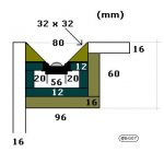
The wood thickness (mounting depth) is 12 mm (MDF)(actually exact ½”) = the height of the cylinder and the diameter of the hole, the cylinder diameter is 36 mm.
The c-c distance is 39 mm leaving a wood thickness between the holes of 3 mm, the square bottom plate (39x39x2 mm) is the guide for how close the T drivers can be mounted and if 1.5 mm on the sides is cut away (I didn’t), the minimum c-c will exactly be 36 mm.
I regret the dim picture and sorry, I never made proper drawings, as this project was a special design for a friend.
The 20 mm is misplaced and is actually the clearance height shown = about 13 mm for the soldering lugs + 7 mm cabling clearing behind the T drivers.
If this distance were made 13 mm, then it would be difficult to solder the wirings and route the many paralleled wires that’s needed for the array.
I marked up precisely the c-c positions on a 1.05m x 12mm x 80 mm piece of MDF, then I used my Dremel Moto-Tool and pre-drilled perpendicular guidance holes = 1 mm for the later use of a rotating hole saw dia 36 mm (actually an 1.5” dia, 1 mm saw blade thickness) that I shrunk to 36.0 mm by pressing a ring of soft steel wire around the saw blade.
I then drilled through half of the distance (6 mm) via both sides.
That’s right it really worked well and a very useful feature, as the center speaker weight is too heavy for one person to carry due to the use of MDF, HDF and the Oak wood and aiming by tilting the whole speaker was not an option especially if placed on a wall.
The angle adjustment made it possible to chose an average listening distance from about 2.5 m to 8+ (m) when placed on the floor.
… Bjorno:I think your wave guide is ingenious.
It looks great and allows crossover as low as 1300 Hz!
You reference the Dayton ND20TB-4 that is no longer available.
Is the Dayton ND20FB-4 the same or similar to the “TB” model you used?…
http://www.partsexpress.com/pe/psho...tnumber=275-035
Thank You redi for your appreciation of the looks.
I have compared data and all the available numbers for both T drivers and found that they are exactly equal; only one letter difference doesn’t make a physical or performance difference at all.
Concerning the 1300Hz I must emphasise that it is a possible acoustical crossover point but its below fs = 1.7kHz where the phase makes a jump.
I think it’s better to crossover at or best just above this resonance peak for easy crossover integration reasons.
…I cannot make out how you mounted the tweeters to your wooden wave guide.
Are they attached with screws?…
Yes and from the rear side of the array.
…What diameter hole did you use for the tweeter to stick through?…
The wood thickness (mounting depth) is 12 mm (MDF)(actually exact ½”) = the height of the cylinder and the diameter of the hole, the cylinder diameter is 36 mm.
The c-c distance is 39 mm leaving a wood thickness between the holes of 3 mm, the square bottom plate (39x39x2 mm) is the guide for how close the T drivers can be mounted and if 1.5 mm on the sides is cut away (I didn’t), the minimum c-c will exactly be 36 mm.
…My eyes are no longer good enough to see what the 20mm dimension in your drawing refers to.
It makes it more difficult since I can’t find a dimensioned drawing of the ND20TB…
I regret the dim picture and sorry, I never made proper drawings, as this project was a special design for a friend.
The 20 mm is misplaced and is actually the clearance height shown = about 13 mm for the soldering lugs + 7 mm cabling clearing behind the T drivers.
If this distance were made 13 mm, then it would be difficult to solder the wirings and route the many paralleled wires that’s needed for the array.
…You must have a good drill press and steady hands. What center to center dimension were you able to achieve?
Did the tight spacing require you to modify the ND20’s mounting plate?…
I marked up precisely the c-c positions on a 1.05m x 12mm x 80 mm piece of MDF, then I used my Dremel Moto-Tool and pre-drilled perpendicular guidance holes = 1 mm for the later use of a rotating hole saw dia 36 mm (actually an 1.5” dia, 1 mm saw blade thickness) that I shrunk to 36.0 mm by pressing a ring of soft steel wire around the saw blade.
I then drilled through half of the distance (6 mm) via both sides.
…I recall seeing another picture of this array in a horizontal center channel array with vented mid drivers mounted below the tweeter array.
I also think I recall reading that you made the tweeter array so the angle could be adjusted.
How did it turn out for actual listening?…
That’s right it really worked well and a very useful feature, as the center speaker weight is too heavy for one person to carry due to the use of MDF, HDF and the Oak wood and aiming by tilting the whole speaker was not an option especially if placed on a wall.
The angle adjustment made it possible to chose an average listening distance from about 2.5 m to 8+ (m) when placed on the floor.
…Did you use the adjustment feature to fine tune the array direction?
My calculations of the main aiming lobe were spot on from the very beginning and the only adjustment I had to do when installing at my friend was the recessing of the tweeter array frame about 0.75 mm inwards as I can recall.
…What is your impression of the ND20 tweeter for a line array?…
I think the sonic quality was absolutely in line and matched well with (surpassing) the ScanSpeak SS D2905/970000 that were used in the mains.
…maghen;
Yes, some progress! I have the 3" drivers and they look very good.
Right now I'm thinking about how to make the baffles and boxes. One thought is to make the entire arrays "curved" to make the distance approximately equal from the most likely listening point to each driver.
However this is not very convenient since it ruins a lot of the line array not having such a small "sweet spot" as a point source...
Maybe you can afford two short wave guided Bessel-lines with 5-7 Dayton ND20FB-4 in each column mounted close to the M: s inner side for early evaluation of the T: s before the decision making of eventually buying more for a full-length line.
http://www.diyaudio.com/forums/attachment.php?postid=961584&stamp=1152883721
The only problem you will face is the sensitivity difference between the M line and the T line.
The later would have a midband sensitivity of about 93 + 6 dB SPL/1m/1W for both the lengths and a maximum power rating of 3.5 x 15 about >= 50 W RMS.
…I'm thinking sealed boxes, 30l for all 20 drivers, perhaps 2000x170x90 mm (90mm baffle width).
I will mount the optional tweeters on a separate baffle to the side of this box.
Is there any reason I shouldn't make such a narrow baffle?…
This is my method too, making the separated lines with minimum widths from the beginning and later when measuring the FR integration with the other lines included, separate more if necessary and or recess one whole line for X-over phase alignment and to adjust the main lobe absolute aiming.
For the baffle step/diffraction effects not known from the beginning it’s also easy to adjust for the best baffle width and side chamfering (T-side) by testing and measuring until all is ok.
b
1(1)
Attachments
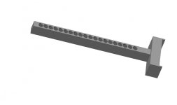
stage 1
This is what stage 1 might look like!
The new thing in this plan is that the "foot" is supposed to be a sealed ~18l enclosure for an 8" Peerless SLS-213-830667 facing downwards. I might end up with a totally different shape as well, this is just one possibility.
This is what stage 1 might look like!
The new thing in this plan is that the "foot" is supposed to be a sealed ~18l enclosure for an 8" Peerless SLS-213-830667 facing downwards. I might end up with a totally different shape as well, this is just one possibility.
Attachments
nasty standing wave?
Will the standing wave really be a problem? The box will be stuffed with dampening wool. I was considering the 20 3" drivers being equal to one larger driver in the same volume. Since the drivers will be placed very closely together, there isn't much room for separating walls...
I was actually considering building separate tube enclosures for each driver, but stuck with the single volume enclosure idea since I was curious about what aperiodic venting might do to the lower end.
power tapering? Post #92 I'm just about to buy the boards for making the cabinets!
Will I run in to trouble using one single cabinet for all 20 drivers? I'm sure it will be fine for "straight" wiring, but what about if I want to "power taper" them?/Magnus
Hi Magnus,
I recommend not using a single cabinet for all drivers, if you want to power taper 20 drivers, you must use separate compartments.
Power tapering with 20 drivers, see pictures 1(6) to 3(6), and my suggestion with 7 T drivers to compliment the 3” drivers; revised picture 4(6) to 6(6).
Nasty standing wave? Post #94
Will the standing wave really be a problem? The box will be stuffed with dampening wool.
I was considering the 20 3" drivers being equal to one larger driver in the same volume.
Since the drivers will be placed very closely together, there isn't much room for separating walls...
It’s not a good idea to put several drivers sharing the same cabinet, use 7 mm plywood (5 plies) for separation of the drivers.
I was actually considering building separate tube enclosures for each driver, but stuck with the single volume enclosure idea since
I was curious about what aperiodic venting might do to the lower end.
Now it looks like you could use 5 compartments if you power taper, but it would be very difficult to port this box properly especially if an aperiodic loading vents is to be used.
Each compartment must be symmetrical for the driver paths CSA --> stuffing-->CSA-->port-->stuffing-->out.
As this cannot be achieved for a row of drivers in the same compartment using only one vent for all, the drivers will sense different acoustic loads, thus should be avoided.
When building arrays I always start making the driver holes at c-c + an mm, then I glue the array sides.
After the glue has dried over night, I continue with the dividers, starting at the middle of the array and only gluing a couple pieces at a time.
The dividers should be secured with hand screw clamps or similar, and a couple of hours should pass before gluing the rest of dividers.
While waiting for the glue to dry and to secure a flat baffle, the baffle should always face a flat surface with heavy weights loading along the whole array or the array should be clamped to a flat surface table or similar.
Hint, spray glue pieces of ‘IKEA’s Barrit’or similar ¼” wool felt on all internal surfaces and the whole array will sound dead when later performing the ‘knock on wood’ test.
b
1(6)
Attachments
- Status
- This old topic is closed. If you want to reopen this topic, contact a moderator using the "Report Post" button.
- Home
- Loudspeakers
- Multi-Way
- which loudspeaker design?