How do you find the ps's performance?
well I can't really comment as this is my first project. I plan to make a SS rectifier and play around with different designs to compare.
but so far no complaints. I get zero hum, music plays as it should through my Aikido 5687 board.
Just a little high frequency hissing but this is due to I think the high gain of the Aikido and the system I'm using it in.
CDP>Aikido (17 gain)> SS power amp.
I need to build a buffer for this set up. The Aikido shouldn't really be in this chain without some modification.
Raypalmer:
If you are using Bas' PS board in either a CLC or a CRC config (Resistor or choke after the first cap (C1), start with Bas's values for C1. After you get the PS up and running, you can vary the value of C1 over a small range (from less than 1uf up to around 8-10uf) to change B+ somewhat.
PSUDII let's you see what's going on, and gives a good approximation of B+, ripple, etc. for each CRC or CLC config.
Things are interelated, so when you change a cap or R value, B+ and ripple usually both change, so you can have hours of fun trying to optimize your PS output with PSUDII.
Look at John Broskie's table in the back of the Aikido manual, it has B+ and anode/cathode current values for different tube operating points. B+ is pretty much between 200V and 300V for all of the tubes listed. Once you have selected your tubes (based on needed gain) select a B+ and current combo out of the table. Keep in mind that if your B+ or current is not spot-on, it will still make beautiful music, just not optimized on paper. The tube current is set by the resistor values in the table.
boywonder said:Raypalmer:
If you are using Bas' PS board
Wait... is there a PCB of this out there I can buy??? I'd much prefer that to point-to-pointing the darn thing.
")
Check out this thread and email Geek to see if he has any more of Bas's Aikido PS PCB's
http://www.diyaudio.com/forums/showthread.php?threadid=115900&highlight=
Also check out this thread for info on the PS boards. This is a long thread and requires lots of wading thru posts.
http://www.diyaudio.com/forums/showthread.php?s=&threadid=60585
http://www.diyaudio.com/forums/showthread.php?threadid=115900&highlight=
Also check out this thread for info on the PS boards. This is a long thread and requires lots of wading thru posts.
http://www.diyaudio.com/forums/showthread.php?s=&threadid=60585
Don't worry mate, I'm still at the hand holding stage.
I bought the whole package as the caps are difficult to get down here in Uruguay.
2 Wima caps, 0.68 and 0.33, were essential for my Aikido set up. C5/C6.
I think the other 6 electrolytics , are for if you use DC heaters (x 4) and a couple if you want to use the Aikido as a headphone amp to bypass the cathode resistors on the lower part of the CF if I remember correctly.
Also were 2 shield caps, 0.47uF 630V. I'm using one on Bas's psu as C1. Always come in handy.
Brit01 said:Don't worry mate, I'm still at the hand holding stage.
I bought the whole package as the caps are difficult to get down here in Uruguay.
2 Wima caps, 0.68 and 0.33, were essential for my Aikido set up. C5/C6.
I think the other 6 electrolytics , are for if you use DC heaters (x 4) and a couple if you want to use the Aikido as a headphone amp to bypass the cathode resistors on the lower part of the CF if I remember correctly.
Also were 2 shield caps, 0.47uF 630V. I'm using one on Bas's psu as C1. Always come in handy.
Brit are you using the Electro Harmonix tubes? Or did you end up going with the octal... I don't remember.
Also, what's your heater arrangement like? I always have trouble picturing the circuit until I get the pcb in hand...
Could you post pics???
raypalmer said:Q: When I go to purchase my Aikido PCB... (I'm going for 9-pin). Should I get the "Supporting and Power Supply Capacitors"?? That is to say will getting those pre-determined values simplify things for me a bit?
Sorry for making you guys hold my hand..
Either way works, I ordered the mono 9-pin kit (2 PCBs) with the resistors/caps, a coupling cap selector and Russian coupling caps. There are places on the boards for 2 coupling caps, so you can use just one, or both with two pre-outs or an output cap selector and one pre-out. very flexible. IIRC the caps were Panasonic and the resistors are vanilla metal film.
Mounting two different caps gives you two flavors to choose from. You can use two of the same value but different brand/type, or use two different values for different tastes.
The input selector Broskie is offering is convenient and inexpensive also. The selectors now come with little PCB's mounted, very wiring friendly.
Building the PSU without Bas' board should a be fairly straightforward, the Aikido manual has a useful, basic design. Using the PCBs and selector switches makes for a tidy layout. I'll hopefully be posting pics of my build soon.
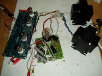
breadboarded at the moment. This shows Bas's psu and the Aikido 5687 board.
I have 2 Svetlana x 6N1P's and 2 x 5687's
Was a bit messy with the axial caps on Bas's psu but that's all I had. Better with some radial as there is limited space.
As boywonder mentions, you can have the 2 coupling caps wired to the switch. I have Auricap and the Russian PIO. Love the PIO btw.
I have 2 Svetlana x 6N1P's and 2 x 5687's
Was a bit messy with the axial caps on Bas's psu but that's all I had. Better with some radial as there is limited space.
As boywonder mentions, you can have the 2 coupling caps wired to the switch. I have Auricap and the Russian PIO. Love the PIO btw.
Attachments
I'm building a 12au7 aikido now.. What's a good starting value for the "xx" cap in the aikido psu? (Assuming I'm shooting for 250v voltage on B+)Brit01 said:hi raypalmer,
Try the psudII software to simulate your B+ and ripple.
I built Bas's psu through trial and error but then downloaded this software just last week and it is superb.
I experimented with different Cap and Resistor sizes and it simulated a B+ of 228 V.
228 V was exactly what I got when I turned it on with only 20mV of ripple .
It will tell you what the max ratings are for the Tube rectifier. The 6X5 is easy to overload. 0.47uF for C1 gave me a reasonable B+.
I currently use a 6X5GT
Caps: 0.47/100/200
Resistors: 1K/500
load: 40mA
Tranny: 275V, 200mA, 51ohms(secondary windings)
Are you planning on a CLC or a CRC?? Are you using the values in Bas' layout for the other caps and resistors? If you are using a choke, what's the H value and resistance? What voltage is your transformer secondary?
Have you played around with PSUDII?
IIRC Bas' schematic shoots for a B+ of 200-210V or so using the recommended transformer, so start there (it won't hurt anything) and bump the first cap value up by 1 uf at a time until you get 250V. Modeling it in PSUD beforehand is a good sanity check to not exceed the forward current of the 6X5.
Check out threads 405-409 of this thread.
http://www.diyaudio.com/forums/showthread.php?s=&threadid=60585&perpage=50&highlight=&pagenumber=9
Sheldon's PSUD model using the equivalent parallel R and C values of the last stages of the PS is what I used and it's fairly accurate for getting in the ballpark.
- Status
- This old topic is closed. If you want to reopen this topic, contact a moderator using the "Report Post" button.
- Home
- Amplifiers
- Tubes / Valves
- Which Aikido pre-amp PCB for a newbie?