peranders said:I love this ppm talk. Have many people are really bothered with a 1000 ppm error? How did you manage before when you used taperecorders and turntables? There we had 1% in deviations!
Hi Per,
Yes, funny. But obviously musicians do not understand that.
Exactly.
Where were these people complaining about perfect pitch 20....30........40 years ago? Never heard them in those days.
No, just the usual crowd, convinced that anyone who hears the effects of jitter just has to be a clockmonger. And therefore flogging a dead horse to make a $.
As if 100 ppm is that hard to do in the first place.
BTW.......what kind of mask did you have in mind????? "Real horror show......", maybe.
Jocko
Jocko Homo said:
BTW.......what kind of mask did you have in mind????? "Real horror show......", maybe.
Jocko
The line reminded me of Nixon and the film Point Break.
How did you manage before when you used taperecorders and turntables? There we had 1% in deviations!
To correct this wow and flutter problem was much easier than to correct harsh sound of high jitter / noisy digital gear. I still love to listen to my turntable and tape deck. It brings me back to reality and guides towards what “a good digital sound” should be like, if that’s possible...
Extreme_Boky
Extreme_Boky said:
To correct this wow and flutter problem was much easier than to correct harsh sound of high jitter / noisy digital gear.
Extreme_Boky
I'd doubt that, but let us agree on the fact that impact differs.
Wow and flutter lead to direct modulation of the analog signal whereas jitter in gives distortion in the D to A conversion.
best
Are you really sure about your statement? How did you correct wow and flutter?
I played a lot with my DENON 3 head / 3 motors tape deck. It is still ultimate analog tape recorder. Not counting reel to reel - they are different league. Replaced flywheel, motor and installed separate power supply. Also played with record / play circuitry a lot.
I also played with my Technics direct drive turntable and used same technics as in DAC's / CD players (clock oscillators) to get very stable speed. Very nice - better than belt driven British stuff.
I may start a thread in analog forums one of these days... maybe even insert some photos. But, is there a REAL interest for this? (apart from your comment). Now that we all forgot about tape decks and turntables.
And, yes, I am really sure!
Extreme_Boky
I'd doubt that, but let us agree on the fact that impact differs.
Of course you would.
You are the most knowledgable guy on forums.
Nice FREE advertising!!!
Extreme_Boky
Extreme_Boky said:
Of course you would.
You are the most knowledgable guy on forums.
Nice FREE advertising!!!
Extreme_Boky
Hi,
Well, there must be more knowledgable people on the forum, nah ?. I am aware of the commercial side effects, the main resaon for me being here is to share knowledge.
By the way, sub LF jitter indeed frequency modulates the playback, similar to what happens in the analog stuff. But we talk serious amounts of jitter here, we encountered that in studio (ordclock) situatons.
best
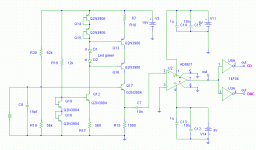
Hello I have anticipated east circuit and I am going to mount it when the components arrive to me, I have a version of the oscillator more outpost than I am not going to put.
This oscillator is twice more express than a normal circuit. I see that the problem of the speed of the used transistors is in if a problem. The transistors with which I have tested are of 300Mhz. I am going to change them by transistors of 5Ghz.
The comparator that I have put is of 4ns. In order to find comparators faster it is necessary to choose them with exit ECL. The exit with 74f04 will be optional.
Attachments
Sabas said:Hello I have anticipated east circuit and I am going to mount it when the components arrive to me, I have a version of the oscillator more outpost than I am not going to put.
This oscillator is twice more express than a normal circuit. I see that the problem of the speed of the used transistors is in if a problem. The transistors with which I have tested are of 300Mhz. I am going to change them by transistors of 5Ghz.
The comparator that I have put is of 4ns. In order to find comparators faster it is necessary to choose them with exit ECL. The exit with 74f04 will be optional.
Hola Sabas,
Que tal ?
The circuit is unusual, in the way that you feed the collector with a current. This contributes to larger Vce variations of the active transistor, which is what you don't want (at least I don't)
Could you explain the backgrounds of the choices made ?
Your english looks the result of an online translator. I remember your own english from earlier threads is better.....
best
Hi Sabas,
It is nice to see fresh new thinking on forums.
For the start, it looks pretty good. My analog days tell me that driving a comparator with low impedance is a good thing, so I would leave everything as is and choose faster and more current drive capable Q17.
I would also consider fixing the current / DC level at pin 2 of your comparator by means of a resistor to ground.
Once you get the prototype going, you'll have to feed all the stages with very clean current, even though you have implemented current sinking/sourcing.
Good luck
Extreme_Boky
The explanation
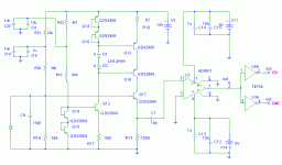
The Q16 transistor is saturated. The Q16 transistor allows to form to the Q13 transistor in a current source. This would not be possible without Q16 and the green leds. The green leds offer a way of unloading for the capacitors of Q13 and Q16. Q12 forms a current source that is pretty and works well.
Advantages:
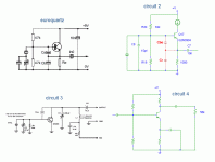
The circuit works with a current source as it shows figure 2. Circuit 4 is a typical circuit that adds a step capacitor to him. In an amplifier of transistors, the power supply provides fixed currents and voltages. The source of alternating produces variations in these currents and voltages. The current source reduces these variations and reduces the distortion of the signal. The power in Q12 is smaller and we reduce the distortion. Circuit 2 is twice more express than the circuit of euroquartz. This is a real advantage. We obtain greater bandwidth and a smaller error of phase.
The half-cycles are more symmetrical and a smaller error in the times of duration of the half-cycles is obtained. We obtain a better cycle 0 and 1 digital.
As It oscillates? I believe that the circuits shown in the image give the explanation
Hello Extreme_Boky
You are right. A circuit RC would be more logical. The AD8611 has Zero Crossing Detector
function. I would like to prove it. An example of this function can be found in LMV7219 and ADCMP580.
Pardon by my ingles. I have forgotten to write. I only read

Attachments
Well, it seems you did the homework just fine.
I would add only one thing, which will help the circuit obtain very low noise figures:
Apart from using very stable and low noise external power supply, I would split R20 in to two resistors in series and decouple the common point of both resistors to ground, or to positive power supply rail - would try both and see which gives lower noise figure. It is a question of which point gives lower noise to start with! It is usually the ground plane - but it may not be! With a good external power supply, it may be the positive (in your case +15V) rail. The decision depends on clock oscillator implementation as well. It may be installed in a noisy ground environment! So, I would probably choose external +15V power supply rail to decouple the common point.
For the given frequency range, I would choose 0.1uF Black Gate NX type, or depending on the PCB layout, try even surface mount capacitors.
FET instead of bipolar transistor Q17 may work really well in given application.
I hope I helped a bit, or at least mentioned some other angles that are very important in obtaining good low noise results.
Extreme_Boky
I would probably choose external +15V power supply rail to decouple the common point.
This doesn't make sense. R20 is already decoupled to +15V.
And splitting it in two only lowers the resistance seen by the xtal, which will reduce Q. FET is good idea, as then these resistances can be made as high as possible. The sharper the Q, the less the oscillation can get pulled by various factors.
jh
Extreme_Boky, thanks to help me
Not if I have understood well. He was this what you said?. In that case it works well.
I have thought to prove with these transistors 5Ghz wideband, BFR92 and BFT92.
It does not desire to me to prove with jfets exoticos wideband. But the idea is interesting. They are more difficult to polarize and this circuit is critical. I can review it to see that it happens.
The step condenser will be that exceeded to me. Vishay MKP1837 1% 10n slew rate 390V/us. Los condensadores de la fuente de alimentación tipo COG.
Attachments
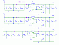
The power supply filtered with ferrites.
The negative power supply will not work, as you've expected. You'll get about -6.2V and I wouldn't wonder, when it's oscillating. Choosing the feedback resistors and the comp cap as you've done gives also a bad load response -> more noise. Paralleling a 100nF and 1nF can also result in ringing. Get rid of the 1nF, it does nothing.
- Status
- This old topic is closed. If you want to reopen this topic, contact a moderator using the "Report Post" button.
- Home
- Source & Line
- Digital Source
- Where there are crystals to buy <10ppm


