Sabas,
The simulation is faulty. What you have is a class B amplifier with a huge dead zone in the middle. Those two diodes on the bases do nothing. In real life, anyway.
This is a common trap. You need to actually build and study the circuit to truly understand. Forget the simulator. Or at least, if you don't believe me, change the output resistance to 1k and try it again.
jh
Hello Extreme_Boky I have seen the Web but I have not seen oscillators with the frequency that I want. Thanks for euroquartz.co.uk have some very interesting circuits.
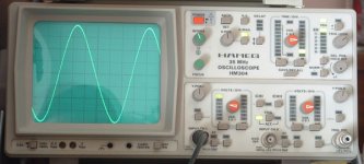
Hello hagtech you are right you cannot be trusted of a simulation I I proved and worked, seemed to me strange. I have proven the circuit and it does not work well. I will give another return him. It had begun to me to oscillate the circuit well but now it does not oscillate to me. I am confused. To see that it happens
Hello hagtech you are right you cannot be trusted of a simulation I I proved and worked, seemed to me strange. I have proven the circuit and it does not work well. I will give another return him. It had begun to me to oscillate the circuit well but now it does not oscillate to me. I am confused. To see that it happens
This is a must read for everyone who wants to play with xtal oscillators:
http://www.euroquartz.co.uk/
In MENU, go to TECHNICAL and download all *.pdf documents. There are 5 total.
What is so special with this documents? It's well known that CMOS and TTL oscillators don't perform well in terms of phase noise and jitter.
bocka said:
What is so special with this documents? It's well known that CMOS and TTL oscillators don't perform well in terms of phase noise and jitter.
The site gives interesting basic information, for starters it is a nice info packet.
When things get serious we better forget the linked company.
best
Hello this it is the new circuit that I have designed. First I proved with jfets and a Colpitts but the signal was not very sine.
Now it lacks the buffer but with this oscillator it does not make lack almost but I must transmit the signal of player to dac and I would like that the exit was balanced.
The circuit I have done it with bc546 and bc556.
")
Now it lacks the buffer but with this oscillator it does not make lack almost but I must transmit the signal of player to dac and I would like that the exit was balanced.
The circuit I have done it with bc546 and bc556.
Attachments

I guess he is trying to make a shunt regulator, but it isn't drawn right. Who knows?
To me it looks like a current source in the collector of Q17 but that does not make sense.
Hi bocka Jocko and Homo
This scheme it is the one of a complete oscillator only needs to power suply done well.
The sense of the diodes and transistors is to form a source of current with a great rejection to the oscillation generated by the crystal.
In R20 and 19 the signal generated by the crystal changes the polarization of Q17. In order to avoid this and so that it is constant the current of Q17 who we generated this source of the current and the distortion diminished to us.
With this circuit sine than with the normal circuits is obtained one more to a signal. The distortion is reduced. The flanks of ascent and slope are simetrics and a signal of clock of more quality is generated.
Before making this circuit I proved with the habitual circuits and they seemed to me bad. This it generates a wave better than a Colpitts
This is a most unusual circuit. I think bocka is correct. Q16 and Q17 are in conflict. You cannot drive the collector of Q17 with a current source - one of the two devices will saturate.
Also, D1, D2, Q16 do nothing. This is NOT a cascode connection. It does absolutely nothing but reduce compliance. You also run an extra current mirror of Q12. Why not just do resistor to ground? The extra stage does nothing for you. Just a lot of extra components that look cool.
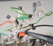
Finally, how can this circuit possibly oscillate? There is no feedback path. What is driving the crystal? Having seen the breadboard, my only guess is some lucky parasitic coupling.
Or perhaps you've discovered an entirely new topology that is sadly misunderstood.
jh
Also, D1, D2, Q16 do nothing. This is NOT a cascode connection. It does absolutely nothing but reduce compliance. You also run an extra current mirror of Q12. Why not just do resistor to ground? The extra stage does nothing for you. Just a lot of extra components that look cool.
Finally, how can this circuit possibly oscillate? There is no feedback path. What is driving the crystal? Having seen the breadboard, my only guess is some lucky parasitic coupling.
Or perhaps you've discovered an entirely new topology that is sadly misunderstood.
jh
peranders said:If you have only one clock source the absolute frequency isn't very important.
Jocko Homo said:The exactitude has nothing to do with it. You are not going to hear the difference if it is 10 ppm or 1000 ppm.
hagtech said:Redbook is +/-100ppm, so it's not a big deal. Certainly not a noticeable pitch change.
Obviously, none of you clockmongers are musicians. People blessed/cursed with perfect pitch can easily recognize pitch differences of 100ppm. If you all accept the Redbook specs for frequency accuracy, why don’t you also accept them for jitter?
Obviously, none of you clockmongers are musicians
Correct. We are actually former musicians.
I'll concede you the point. Perhaps this is audible to some. A +100ppm error for a 1000Hz tone pushes it up to 1000.1Hz. Compare a C6 at 1046.5Hz to a C6# 1108.7, a 62.2Hz change, or roughly +60,000ppm. We can all hear that.
I'm pretty sure a master tape won't have such absolute accuracy. Especially after it has aged a bit.
jh
It is generally accepted that at the limit some trained musicians can detect a one cent deviation in frequency. This is a ratio of 1.000577 to 1. One cent is thus 577 ppm.
However even with perfect pitch it is unlikely that any musician can detect a one cent change of pitch in isolation - i.e. listening to music, where the entire piece is transposed one cent, with no external reference. The detection of a one cent difference requires it to be an active change in some form of musical context. The vast majority of real (as opposed to synthesised) instruments will change in pitch much more than this in normal use.
One might point to any number of albums released over the years that have had quite gross errors in mastering frequency, sometimes up to a full semitone out, that went undetected for ages. As mentioned above, in the days of analog tape recording there would be no chance whatsoever that an accuracy of one cent could be maintained across the recording chain, any turntable you could think of would suffer a greater change. The thermal coefficient of expansion of aluminium is 23 ppm per degree C. That alone might be a clue.
Jocko Homo said:I am not a clockmonger.
Where can I buy a Jocko mask?
Ulas said:
Obviously, none of you clockmongers are musicians. People blessed/cursed with perfect pitch can easily recognize pitch differences of 100ppm. If you all accept the Redbook specs for frequency accuracy, why don’t you also accept them for jitter?
Obviously ?
I know a bit of the redbook.
The +/- 100ppm is a static spec, the DC component of the jitter. The rest of its' spectral content affects the conversion: distortion is the result.
I sincerely hope you understand above, otherwise you'll limit yourself with perfect pitch priciples while accepting distortions that even non-musicians can easilly hear.
best
- Status
- This old topic is closed. If you want to reopen this topic, contact a moderator using the "Report Post" button.
- Home
- Source & Line
- Digital Source
- Where there are crystals to buy <10ppm