Yes; at least in nearly all cases. Resistors are usually color coded. Most capacitors have their values written in numbers on them.If I pull the cover will each of the components have detail on them that will tell me what they are?
In short: no. If you're more or less happy with it as it is, I'd recommend not changing it.It does sound like this could be improved significantly but would the suggestions be in the realm of a complete novice to undertake?
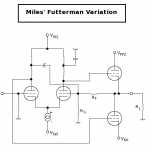
This is a weird circuit. At first I thought it might be a strange headphone amp, but as a line stage it is even weirder. It seems to have been 'designed' by someone who thinks that if some valves are good, more valves are better! Typical Chinese junk, sadly badge-engineered by a Western company.
The phase splitter is followed by an unbalanced driver stage. It is unbalanced because only one side has its anode load bootstrapped from the output stage. The output stage is heavily loaded by the 1K5(?) resistor feeding the bootstrapped driver side.
I would expect quite high distortion, but the high gain is then thrown away by heavy negative feedback. The net result will probably measure quite well, but sound horrible.
You mentioned $1500 as the original price. Anyone who paid more than $15 for this was a mug, and possibly deaf too.
Stop Press: the feedback appears to be positive, so this circuit cannot possibly work as shown!
Being a complete novice with little or no understanding of circuits means I am a bit at a loss here.
If I pull the cover will each of the components have detail on them that will tell me what they are? I could do that and then write them down if that would help in understanding the circuitry better?
It does sound like this could be improved significantly but would the suggestions be in the realm of a complete novice to undertake?
It isn't likely that you'll be able to fix it on your own.
Last edited:
This is a weird circuit. At first I thought it might be a strange headphone amp, but as a line stage it is even weirder. It seems to have been 'designed' by someone who thinks that if some valves are good, more valves are better! Typical Chinese junk, sadly badge-engineered by a Western company.
The phase splitter is followed by an unbalanced driver stage. It is unbalanced because only one side has its anode load bootstrapped from the output stage. The output stage is heavily loaded by the 1K5(?) resistor feeding the bootstrapped driver side.
I would expect quite high distortion, but the high gain is then thrown away by heavy negative feedback. The net result will probably measure quite well, but sound horrible.
You mentioned $1500 as the original price. Anyone who paid more than $15 for this was a mug, and possibly deaf too.
Stop Press: the feedback appears to be positive, so this circuit cannot possibly work as shown!
Not only it's a very bad design, probably the schematic is wrong.
I'd start over with an Aikido line stage or perhaps a basic 12B4 line stage or something similar. (Maybe even one of the bottlehead kits.)
Find someone locally who is willing to put something together for you. You'll be happier in the long run.
This line stage is excessively complex for the job it needs to do, and the schematic as drawn is clearly incorrect.
The build quality also leaves quite a lot to be desired..
Depending on your willingness to learn, and ability to deal with some frustration it might be worth your while to learn what makes this stuff tick. If so I'd start by picking up a copy of Morgan Jones' "Valve Amplifiers, 3rd Edition" - you may also need to do a little research to understand some basic electronic concepts, here google can help. Once you learn a little you might want to try your hand at building something, nothing more satisfying once you get it working. You just need to educate yourself, and lots of people here will probably be willing to help.
That's a good catch, actually. As drawn, there's positive feedback.
~Tom
The hollow state OTL bug is biting again, and I've looked into doing the same thing to balance a stack of 6AS7s, inverted Futterman style. Use an LTP splitter or driver, with the NFB fed back to the plate side to balance the two phases as effective cathode followers.
Dunnow if I'll actually do it, or decide in favor of a hybrid Cyclotron (glass up front, lateral MOSFETs on the back end.) All those 6AS7s get plenty hot, and require some bigamps to run the heaters.
Okay, so I just pulled the cover and also stopped by the library for some reading material.
They don't have the Jones book sadly but I did get:
How to read schematics by Herrington
Repairing Home Audio systems by Ecklund
The beginners handbook of electronics by Olsen/Mims
I'll see if I can find the Morgan book in the library system and order it.
What an experience THIS is turning out to be. I'm grateful that you are taking the time to give helpful feedback (and honest feedback).
As odd as it might appear it actually sounds pretty decent. It doesn't have a lot of warmth and the bass is on the thin side but the distortion is really quite low.
I imagine once I compare it to something that is built better and designed better I will have a point of reference that will put your comment into context. Of course, I could just be going deaf
I imagine once I compare it to something that is built better and designed better I will have a point of reference that will put your comment into context. Of course, I could just be going deaf
This is a weird circuit. At first I thought it might be a strange headphone amp, but as a line stage it is even weirder. It seems to have been 'designed' by someone who thinks that if some valves are good, more valves are better! Typical Chinese junk, sadly badge-engineered by a Western company.
The phase splitter is followed by an unbalanced driver stage. It is unbalanced because only one side has its anode load bootstrapped from the output stage. The output stage is heavily loaded by the 1K5(?) resistor feeding the bootstrapped driver side.
I would expect quite high distortion, but the high gain is then thrown away by heavy negative feedback. The net result will probably measure quite well, but sound horrible.
You mentioned $1500 as the original price. Anyone who paid more than $15 for this was a mug, and possibly deaf too.
Stop Press: the feedback appears to be positive, so this circuit cannot possibly work as shown!
The phase splitter is followed by an unbalanced driver stage. It is unbalanced because only one side has its anode load bootstrapped from the output stage. The output stage is heavily loaded by the 1K5(?) resistor feeding the bootstrapped driver side.
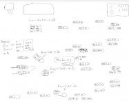
You have to remember that that schemo is totally EFFFF-ed up. Here is what it should look like (Attached: nonessential parts omitted). The 1K5 resistors don't excessively load anything. You can't apply the feedback directly to the plate since it's a Lo-Z node, and will absolutely kill off any possibility of gain. You can't connect to the far side of the plate resistor either, since you'd effectively short out your output (Vpp is at AC ground). So you need to split the plate loads to give the NFB a reasonable load. (4K7 against 8R gives a voltage divider gain of 0.998).
The other phase requires the same plate resistors for DC balance, and the junction is bypassed to AC ground to make the plate loads equal at signal frequencies.
This gets you the same sort of 100% NFB needed to turn the bottom triode into an effective cathode follower to improve phase-to-phase symmetry, and drop the Zo in the same manner as an Inverted Futterman stage would do.
Positive feedback to the upper triode would turn it into an effective grounded cathode stage, also restoring balance, but in the wrong direction, making Zo much higher than it needs to be.
Attachments
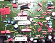
Here is a close up of the board and my incredibly detailed and clearly knowledgeable attempt to provide more info.
Does this help?
The photo of the board helps... Someone with half a clue "upgraded" the caps to nice Wima polypropylene. I say half a clue because whoever did it had enough forethought to use heatshrink tubing but the soldering is horrible. I see several cold solder joints and points that need a good cleaning with flux remover. Those could cause some howling.
From some of the comments it seems to me that it is surprising it plays at all
Not really... We're all sort of assuming that it's built according to the schematic. If the amp plays, that can't be the case for reasons outlined above.
Unless you're madly in love with the sound of this amp, I'd take the PCB out and repurpose the chassis. You will probably be able to use the power supply for a different project. Turn it into a learning experience and build a tube preamp.
~Tom
Okay; must research "flux remover"!!
So I guess if I am going to take on a project I need to get the Morgan book, right? Or is there a "Dummies guide to tube amp building" that I should get?
In the short term it will have to stay in use as I don't have any money to be buying parts but you guys have certainly given me plenty to consider AND plenty of helpful advice.
Can things like the Wima caps be reused or is it not really worth it?
Anyone in the NJ area want to apprentice a forty six and a half year old guy with almost no skill in electronics?
Okay; must research "flux remover"!!
Flux Remover, 5 Oz - Flux Removers - Supplies - Power Tools & Metalworking : Grainger Industrial Supply
It's mostly acetone based. You could use acetone to get the flux off. Then follow with an isopropyl alcohol rinse. Watch out around old polystyrene caps as acetone dissolves polystyrene.
So I guess if I am going to take on a project I need to get the Morgan book, right? Or is there a "Dummies guide to tube amp building" that I should get?
Morgan Jones has two books. Valve Amplifiers and Building Valve Amplifiers. I think you'd benefit from both. If you're strapped for cash get Valve Amplifiers first. Also check out the "which book should I get" thread currently running. It's a common questions so some forum searching is in order.
~Tom
moggi, having a lot of experience as a professional electronics technician, I warmly advise you not to touch anything, not before you'll master the basics of electricity and electronics. The books about design and building of tube amplifiers will not do you much good before you'll know at least basic electronics. For a technician, trying to repair a device someone has fiddled with is 1000 more difficult than repairing unmodified device. Before you know for sure what you are doing, how and why, any tampering may bring about only damage.
As for explaining the concept, yes. But don't try to build it as drawn, you'd need the extra parts (they provide voltage level shifting biasing).(Attached: nonessential parts omitted)
You can be sure my fear of electrocution is far greater than my desire to start ripping it apartmoggi, having a lot of experience as a professional electronics technician, I warmly advise you not to touch anything, not before you'll master the basics of electricity and electronics. The books about design and building of tube amplifiers will not do you much good before you'll know at least basic electronics. For a technician, trying to repair a device someone has fiddled with is 1000 more difficult than repairing unmodified device. Before you know for sure what you are doing, how and why, any tampering may bring about only damage.
I appreciate the warning though, at these voltages you can't reiterate that enough.


So what would it look like with all the parts includedYou have to remember that that schemo is totally EFFFF-ed up. Here is what it should look like (Attached: nonessential parts omitted). The 1K5 resistors don't excessively load anything. You can't apply the feedback directly to the plate since it's a Lo-Z node, and will absolutely kill off any possibility of gain. You can't connect to the far side of the plate resistor either, since you'd effectively short out your output (Vpp is at AC ground). So you need to split the plate loads to give the NFB a reasonable load. (4K7 against 8R gives a voltage divider gain of 0.998).
The other phase requires the same plate resistors for DC balance, and the junction is bypassed to AC ground to make the plate loads equal at signal frequencies.
This gets you the same sort of 100% NFB needed to turn the bottom triode into an effective cathode follower to improve phase-to-phase symmetry, and drop the Zo in the same manner as an Inverted Futterman stage would do.
Positive feedback to the upper triode would turn it into an effective grounded cathode stage, also restoring balance, but in the wrong direction, making Zo much higher than it needs to be.
Well if you don't ask.........
- Status
- This old topic is closed. If you want to reopen this topic, contact a moderator using the "Report Post" button.
- Home
- Amplifiers
- Tubes / Valves
- What's wrong with this?