I got some comments on another forum about poor design and it most likely is but what simple things would you change to make it a better design?
Sorry the schematic is poor but it probably will make sense to those of you who understand this stuff.
Thanks.
Sorry the schematic is poor but it probably will make sense to those of you who understand this stuff.
Thanks.
Attachments
I'm by no means an expert, but I can tell that the schematic is of poor quality. All parts values are illegible ") Sorry, couldn't resist.
Sorry, couldn't resist.
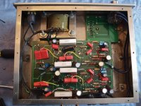
I see an integrated amp that accepts a balanced input through a transformer. I suppose the balanced input could have been used to drive separate amplification stages right up to the output, eliminating the concertina phase splitter. This is not a simple modification though; it would require re-engineering roughly half of the amplifier circuit.
Also, I suspect that the output impedance of this circuit is actually a lot higher than your average 8Ohm speaker, so there is probably an impedance mismatch.
I guess the easiest modifications would be to change some coupling caps. I'd start right at the end, where there's an electrolytic cap that I'm sure many people on these boards have a very explicit opinion about. The first thing they'd probably suggest is to replace it and bypass it with a small value foil cap to enhance the high frequencies. The coupling caps between the phase inverter and the driver tubes could be replaced as well. Personally, I'm skeptical regarding the impact of such modifications, but two things are certain: (1) many people claim outstanding results if 'audophile' caps are used, and (2) those audiophile/phool caps can cost an arm and a leg.
But let me pass the question back to you: is there anything in particular you don't like in this amplifier?
Sorry, couldn't resist.I see an integrated amp that accepts a balanced input through a transformer. I suppose the balanced input could have been used to drive separate amplification stages right up to the output, eliminating the concertina phase splitter. This is not a simple modification though; it would require re-engineering roughly half of the amplifier circuit.
Also, I suspect that the output impedance of this circuit is actually a lot higher than your average 8Ohm speaker, so there is probably an impedance mismatch.
I guess the easiest modifications would be to change some coupling caps. I'd start right at the end, where there's an electrolytic cap that I'm sure many people on these boards have a very explicit opinion about. The first thing they'd probably suggest is to replace it and bypass it with a small value foil cap to enhance the high frequencies. The coupling caps between the phase inverter and the driver tubes could be replaced as well. Personally, I'm skeptical regarding the impact of such modifications, but two things are certain: (1) many people claim outstanding results if 'audophile' caps are used, and (2) those audiophile/phool caps can cost an arm and a leg.
But let me pass the question back to you: is there anything in particular you don't like in this amplifier?
Mastodon, other than a buzz/hum in the right channel (using the RCA not balanced output), I rather like the sound it produces HOWEVER I have nothing to compare it to.
Also, I think the concern expressed elsewhere was to do with heat and how component layout inside the preamp would generate a lot of heat and create an early death for many of the electrolytic's.
I am into spending as little as possible but was concerned that maybe if I din't tackle a potential issue now I would end up paying more in the future.
I look forward to hearing opinions on the electrolytic cap and coupling caps you mentioned (are we venturing into the same world as 'power cables make a difference'? Polarized opinions usually!!)
Thanks for your prompt response.
I have scanned the schematic and penciled in what I can read and will upload it.
Don't do any modifications to the circuit until you've fixed the hum issue. Unless there's a defective component somewhere, random component swapping will do nothing to cure the buzz.
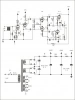
It looks like a fairly standard push-pull design to me. I'm curious about what appears to be a gain stage after the phase splitter (2nd tube from the input).
~Tom
It looks like a fairly standard push-pull design to me. I'm curious about what appears to be a gain stage after the phase splitter (2nd tube from the input).
~Tom
I was hoping I would get that looked at this week but that isn't going to happen. I am hopeful that next Wednesday or Thursday a friend of a friend who knows his stuff will give it the once over.
Your comment about the design is one of the reasons I posted here. I was wondering if there was anything odd or that might peak curiosity (as well as finding out if I shouldn't risk having it on for more than a few hours at a time). I couldn't find anything to compare to this precise layout in all my searches.
Thanks for the response, Tom.
Don't do any modifications to the circuit until you've fixed the hum issue. Unless there's a defective component somewhere, random component swapping will do nothing to cure the buzz.
It looks like a fairly standard push-pull design to me. I'm curious about what appears to be a gain stage after the phase splitter (2nd tube from the input).
Re audiophool/boutique caps.... It's the dielectric and parasitic elements of the caps that matter. I use polypropylene caps for coupling caps due to the performance of the dielectric - extremely low loss, low dielectric absorption, and low ESR (equivalent series resistance), hence, low distortion. There are differences between brands but for foil caps of a given dielectric the differences boil down to differences in winding style and terminations. These effects are captured in the ESR and ESL (equivalent series inductance) or SRF (self-resonant frequency) of the caps.
Whether you want to use boutique caps or $0.50 metalized polypropylene caps from Digikey and other sources is up to you. One thing I've noticed is that the $0.50 cent caps tend to be better characterized than the $50 boutique caps. It's easy to measure the ESR, ESL, SRF, loss tangent, etc. if you have the right equipment. Personally, I use the HP 4194A impedance analyzer I have access to at work... Generally I find that the $0.50 caps are better characterized and have datasheets available for them but the $50 boutique caps offer no data whatsoever. They claim to work purely on patent pending magic. Sorry. That doesn't work for me. I'm a scientist and an engineer. I need claims that are backed up by valid data. Others are free to disagree with me on this.
~Tom

As for the hum/buzz in one channel, that power transformer looks kinda close to one of the channels. Is that the channel with the hum/buzz? There may be stray magnetic field leaking from the transformer and coupling into some of that channel's wiring. You may need to change the location of that transformer.
The schematic was sent to me from the company who sells (or sold, as it is now discontinued) the item. It was likely built in China for them and badged. The company in Canada is called Tubemagic.
It may be this is not the correct schematic
It cannot be the correct schematics, it isn't a correct schematics for any amplifier. Just for instance, it's impossible that electrolytic capacitors rated 150 Volt will be fed with voltages between 382 and 206 Volt. It's also impossible that in the PSU 292 Volt will come AFTER the 206 Volt. This schematics is misleading, probably intentionally.
It cannot be the correct schematics, it isn't a correct schematics for any amplifier. Just for instance, it's impossible that electrolytic capacitors rated 150 Volt will be fed with voltages between 382 and 206 Volt. It's also impossible that in the PSU 292 Volt will come AFTER the 206 Volt. This schematics is misleading, probably intentionally.
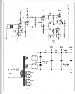
I think it's supposed to be 296 V and 292 V. Not 206 V and 292 V. The 9 in '292' is a bit more clear on the phase splitter. You're right about the 150 V caps, though... They should be 450 V caps minimum.
Having looked at it a bit closer now, I don't like the circuit, though. As far as OTL circuits, it's probably the worst I've seen because of all the coupling caps carrying rather large signal currents (including the output current). But I don't see any reason it wouldn't work as an amplifier. I do admit, though, that I haven't analyzed the last bit of the output stage in details.
~Tom
Last edited:
On the original schematic, those look more like 4's than 1's. Anyway, you'd want 450V caps there. Oh, be careful poking around in there, 400VDC can kill.
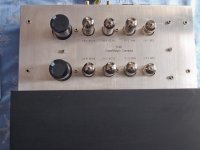
Is this thing used as a buffer, or does it drive speakers, or headphones? I don't see a volume control anywhere, Oh wait, I think I do see one at the upper right of the under chassis pix).
Is this thing used as a buffer, or does it drive speakers, or headphones? I don't see a volume control anywhere, Oh wait, I think I do see one at the upper right of the under chassis pix).
Last edited:
On the original schematic, those look more like 4's than 1's. Anyway, you'd want 450V caps there. Oh, be careful poking around in there, 400VDC can kill.
Is this thing used as a buffer, or does it drive speakers, or headphones? I don't see a volume control anywhere, Oh wait, I think I do see one at the upper right of the under chassis pix).
It has an Stepped Laddered Attenuator for volume.
I run a Vista phono stage through it and the amplification is supplied by a pair of Marantz MA500 SS monoblocks.
Any poking around has been done with the unit unplugged and left for an hour.
I think it's supposed to be 296 V and 292 V. Not 206 V and 292 V. The 9 in '292' is a bit more clear on the phase splitter. You're right about the 150 V caps, though... They should be 450 V caps minimum.
Having looked at it a bit closer now, I don't like the circuit, though. As far as OTL circuits, it's probably the worst I've seen because of all the coupling caps carrying rather large signal currents (including the output current). But I don't see any reason it wouldn't work as an amplifier. I do admit, though, that I haven't analyzed the last bit of the output stage in details.
~Tom
I'm interested to find out if this can be made into an improved performer. I do wish I had a clear schematic and I do think that my misinterpretation of some of the numbers has added confusion.
I hope to see Roger Gibboni of Rogershifidelity next week (he is the 'friend of a friend') so maybe he can make some suggestions as to how to get rid of the hum and improve this setup.
Here is a link to the website where the item was originally sold TubeMagic Products Amazing to think this originally sold for $1500 - can to me for free.
It cannot be the correct schematics, it isn't a correct schematics for any amplifier.
It sure isn't. The feedback has to go to the bottom, grounded cathode triode to turn it into a cathode follower (in effect) not the upper triode that's already a cathode follower.
You guys lost me about.........er, 24 hours ago
I guess we cannot tell from the image what is what?
I could get a high res. one and host it off-site if anyone thought that would help?
I could even drop round and see someone in NJ if they are interested in seeing it up close.
Does anyone find the choice of tubes to be odd? They don't seem to be standard fare!
It sure isn't. The feedback has to go to the bottom, grounded cathode triode to turn it into a cathode follower (in effect) not the upper triode that's already a cathode follower.
That's a good catch, actually. As drawn, there's positive feedback.
Did I understand correctly that this is a LINE STAGE!? Also known as a preamp? That's crazy! Why would anybody use a topology like that for a line stage?
Unless I'm mistaken, I'd just plunk down a couple of 6SN7's or 6J5's and build something better.
~Tom
I bet the hum is just due to insufficient power supply filtering. Some measurements using a 'scope would clear the issue up, but I assume the OP has no access to one... What's the value of the first resistor in the power supply marked with a *?
Also, I'm not really happy with those two capacitors right after the bridge rectifiers; it's kind of an odd arrangement in any case. Why not put the windings in series, use one bridge rectifier and put a voltage divider across those first two caps? The voltage divider will act as a bleeder as well, which currently seems to be absent.
Perhaps an improved schematic with readable parts values in the amplifier section would be nice too. In case people here want to really dive into the circuit, so to speak.
Is it alright if I agree? Don't really feel like disagreeing on this one.I need claims that are backed up by valid data. Others are free to disagree with me on this.
Being a complete novice with little or no understanding of circuits means I am a bit at a loss here.
If I pull the cover will each of the components have detail on them that will tell me what they are? I could do that and then write them down if that would help in understanding the circuitry better?
It does sound like this could be improved significantly but would the suggestions be in the realm of a complete novice to undertake?
- Status
- This old topic is closed. If you want to reopen this topic, contact a moderator using the "Report Post" button.
- Home
- Amplifiers
- Tubes / Valves
- What's wrong with this?