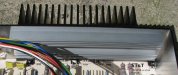
Heat Sink Details
4.25" wide x 2" high fins x 1" deep fins -- 19 total Black unit
[around 67 sq. in.]
plus
5.25" x 1" x 1/2" sub fin Silver unit
I've run the unit bridged mono into 32 ohms at 56 V (98W) fins were
untouchable so ran a high capacity fan to keep it cool. No bad smells
and still works. Undersized heatsink it is - - TIPs, Vbe transistors, and thermistor
all mounted (TIPs with screws and pads, Vbe pushed close with compound, and
thermistor pressed between heatsink and PCB with compound and foam.
65W max per TIP transistor = 260W total max needed to dissipate.
Attachments
Measurements with 60Hz sine wave
Right
Input: 473mV [Vgain=15.64dB]
Output: 2.863V (8 ohms resistive)
R223 & R224: 34.6mV [emitter]
R221: 666mV
R219: 1.4mV [output base resistor]
R220: 1.5mV [output base resistor]
R217: 1.158V [Vbe bias]
R218: 627mV [Vbe bias]
R213: 2.445V [NFB]
R214: 437mV [NFB=16.33dB]
Left
Input: 460mV [Vgain=15.82dB]
Output: 2.843V (8 ohms resistive)
R123 & R124: 32.5mV [emitter]
R121: 663mV
R119: 1.4mV [output base resistor]
R120: 1.4mV [output base resistor]
R117: 1.154V [Vbe bias]
R118: 622mV [Vbe bias]
R113: 2.717V [NFB]
R114: 438mV [NFB=16.24dB]
I tried 1950 ohms which gave around 10mV, but the undersized heatsink was
around 100 F instead of 82 F at 7.5mV(68 F room temp). Once I set up the
forced air cooling I can up the bias. . . 15mV (68mA).
Why 15mV may I ask. . . seems there is a diminishing return. . . is this the point
between high quality reproduction and "I don't want to listen to this crap any more."
around 100 F instead of 82 F at 7.5mV(68 F room temp). Once I set up the
forced air cooling I can up the bias. . . 15mV (68mA).
Why 15mV may I ask. . . seems there is a diminishing return. . . is this the point
between high quality reproduction and "I don't want to listen to this crap any more."
You might want to read the essential D. Self article on power amplifier distortion. It contains some information on the optimum bias for an output stage.gni said:...Why 15mV may I ask. . . seems there is a diminishing return. . . is this the point
between high quality reproduction and "I don't want to listen to this crap any more."
Thank you Mr. Evil and John Curl. Slowly making into Blowtorch thread (17,570 replies). Will try the "essential D. Self article on power amplifier distortion."
Thank-you for the sources.
John, you seem to know a fair amount about circuit design. You and AndrewT
should get together and design a new amp. . .
Thank-you for the sources.
John, you seem to know a fair amount about circuit design. You and AndrewT
should get together and design a new amp. . .
Yet you know what you are talking about.
(I just made the connection of John Curl in last post).
Checked bias - Room Temp 61 F (16 C)
Right - 4.5mV
Left - 4.3mV
Last Night the room was up to 71 F (22 C) and the right channel was
up to 9.1mV and left was 8.6mV.
The bias was double with a 10 degree F change (6 C change). Will the bias
continue to change - 18mV at 81 F (27 C) and 36mV at 91 F (33 C). At some
point the heatsink won't really be radiating the heat anymore.
Thermal runaway?
Maybe with the original value of 2.7k ohms will cause the bias
current at +100 F (38 C). to slightly rise.
Designed to not self-destruct due to the under-sized heatsink.
I forgot to mention that the Vbe multiplier must monitor the temperature of the output stage.Change the heatsink for one with 4times the dissipation capacity.
Strange, Radioshack underbiased this amp just so they could
use a cheap , undersized heatsink..
As far as the dual differential amplifier topology being RIP..
BS , many good designs (the leach included) are based on
this method and are stable and musical.
I would not really rate this one , as economics were more
of a factor in this case..
OS
use a cheap , undersized heatsink..
As far as the dual differential amplifier topology being RIP..
BS , many good designs (the leach included) are based on
this method and are stable and musical.
I would not really rate this one , as economics were more
of a factor in this case..
OS
ostripper said:Strange, Radioshack underbiased this amp just so they could
use a cheap , undersized heatsink..
You say that as if it's the first time you've ever seen a major manufacturer do that. I see nothing "strange" about it.
I like symmetrical LTPs, but why use one and then go and use only resistors for tails instead of current sources? It should be possible to get better performance for the same component count from a single LTP + current source than symmetrical LTP + resistors.ostripper said:...As far as the dual differential amplifier topology being RIP..
BS , many good designs (the leach included) are based on
this method and are stable and musical...
- Status
- This old topic is closed. If you want to reopen this topic, contact a moderator using the "Report Post" button.
- Home
- Amplifiers
- Solid State
- What's this Amplifier Design