I think it looks good to me. . .I could always remove the protection circuit. . .
this unit is my 'test' unit that I can do anything. The
schematic doesn't have it but it is there. I can email
the whole thing but it is 2MB.
The result for 4 ohms seems unreasonable.
4 ohms load
11.93V @ 60Hz (trip protection) 2.98A and 35.58W
15.54V @ 120Hz (trip protection) 3.89A and 60.37W
24.25V @ 1001Hz (trip protection) 6A and 147W
This amp is for testing. . .it doesn't matter if it
ends in a shower of sparks. . .I have safety glasses.
My rotel has no safety protection(it would self destruct at a
short). Let's see what kind of cajonies this amp has. I promise
to fan cool the heck out of the heat sinks and plexiglas shield it.
I'll even post pics.
My living will is up to date.
ends in a shower of sparks. . .I have safety glasses.
My rotel has no safety protection(it would self destruct at a
short). Let's see what kind of cajonies this amp has. I promise
to fan cool the heck out of the heat sinks and plexiglas shield it.
I'll even post pics.
My living will is up to date.
AndrewT said:I wonder if the LF is tripping some kind of DC detection circuit?
The prot circuits look like it has a pretty standard timing capacitor. The trip thresshold shifts higher at high frequency/short duration in an attempt to better track the thermal response of the transistors. I s/b is less at 100ms than it is at 1 ms.
gni said:I think it looks good to me. . .I could always remove the protection circuit. . .
this unit is my 'test' unit that I can do anything. The
schematic doesn't have it but it is there. I can email
the whole thing but it is 2MB.
The result for 4 ohms seems unreasonable.
4 ohms load
11.93V @ 60Hz (trip protection) 2.98A and 35.58W
15.54V @ 120Hz (trip protection) 3.89A and 60.37W
24.25V @ 1001Hz (trip protection) 6A and 147W
It is pretty unreasonable for a 4 ohm load. Unfortunately, that's all that little TIP41/42 pair can do without going poof. I've got an idea - you may want to try using some of the new Fairchild outputs before doing this. They have a version of the C5200/A1943 pair in a TO-220! Cool the heck out of it, and it might be able to take quite a beating.
This is a 15 dollar amp. . . this one (I have 4 more) is going
the way of the Raphus Cucullatus one day or another. I have
changed the bias and the input filter to my satisfaction. The
protection circuit is optional; you build an amp first, then design the
protection to the level of cost--this one has thermal, DC fault, and
short-circuit (I think--therefore I shall not touch).
I read the following:
Leach Amp Protection Circuit
http://users.ece.gatech.edu/~mleach/lowtim/prot.html
there is one resistor missing in each half of the protection circuit.gni said:I read the following:
Leach Amp Protection Circuit
http://users.ece.gatech.edu/~mleach/lowtim/prot.html
It gives the IV part of the protection locus.
Read the Leach clone threads and PCB layouts for the location of the extra resistor.
Freq Volts out dB
10 Hz 1.54 V -10.246585583
15 Hz 2.49 V -6.0730130581
20 Hz 3.17 V -3.9758147556
25 Hz 3.62 V -2.8228285893
30 Hz 3.92 V -2.1312786596
35 Hz 4.14 V -1.6569931776
40 Hz 4.29 V -1.3478541563
45 Hz 4.49 V -0.95207317993
50 Hz 4.58 V -0.77969043992
55 Hz 4.64 V -0.6666403889
60 Hz 4.69 V -0.5735431457
65 Hz 4.74 V -0.48143316652
70 Hz 4.77 V -0.4266324192
75 Hz 4.79 V -0.39028973171
80 Hz 4.82 V -0.33605923522
85 Hz 4.84 V -0.30009276711
90 Hz 4.85 V -0.28216522795
95 Hz 4.87 V -0.24642077571
101 Hz 4.88 V -0.22860355995
105 Hz 4.89 V -0.21082281753
110 Hz 4.9 V -0.19307839943
115 Hz 4.91 V -0.17537015754
120 Hz 4.92 V -0.15769794465
125 Hz 4.92 V -0.15769794465
150 Hz 4.94 V -0.12246102153
201 Hz 4.96 V -0.0873664702
301 Hz 4.98 V -0.05241314481
401 Hz 4.99 V -0.03498908753
501 Hz 5.01 V -0.00024548266
601 Hz 5.01 V -0.00024548266
701 Hz 5 V -0.01759991328
801 Hz 5.01 V -0.00024548266
901 Hz 5.01 V -0.00024548266
1001 Hz 5.01 V -0.00024548266
2001 Hz 5 V -0.01759991328
3001 Hz 4.91 V -0.17537015754
4001 Hz 4.84 V -0.30009276711
5001 Hz 4.83 V -0.31805738497
6001 Hz 4.8 V -0.37217525249
7001 Hz 4.69 V -0.5735431457
8001 Hz 4.62 V -0.70416048888
9001 Hz 4.6 V -0.74184336637
9999 Hz 4.51 V -0.91346916244
11999 Hz 3.96 V -2.0430962815
13999 Hz 3.41 V -3.3419124202
15999 Hz 2.82 V -4.9920178336
17999 Hz 2.12 V -7.4702827814
19999 Hz 2.06 V -7.7196555926
Here is a bridged mono connection with the addition
of the 5.6k from the output of the left channel to
the backside of the LTP of the right channel. Also
there is a 100 ohm resistor across the input of
the right channel.
The DC offset is now 155mV. The offset is positive
with reference to the left channel. Before the DC
offset was well behaved.
Question: how should I go about reducing the DC offset?
Should I adjust the value of the bridging resistor?
Currently I am testing into a 32 ohm (100 W)dummy load.
Attachments
Here is version 6 of the mods. I have removed all 'extra' parts from
the board but left the outputs to the left channel. I think the drawing
speaks for itself. Testing for thermal runaway as I type. The physical
layout could be a problem; the bias transistor on the heatsink is between
the main channel NPN and PNP outputs; while the second pair of output transistors are off to the right. I will upload pics tomorrow. Currently the
bias is around 8mV to 9mV (36mA to 41mA on the 0.22 ohm output resistors). Room temp is about 68 degrees Fahrenheit (20 Celsius).
PS - the bridge version 5 didn't work as well as planned.
Attachments
Last edited:
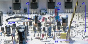
#1 removed components from unused channel
#2 bias 15-turn adjustment pot addition
#3 unused channel output paralleled into main output
#4 removed unused channel output relay RY2
#5 unbalanced input
Two jumper wires soldered under board to connect
the paralleled output transistors to the main outputs.
Protection circuit still operating.
Bias transistor Q111 is between the two main outputs (Q109,Q110).
The paralleled outputs Q109 and Q210 are sharing the bias transistor Q111.
Bias is set to 10mV +/-1mV (45.4mA) for each output. Total bias current for all output devices is 182mA.
Attachments
Last edited:
- Status
- This old topic is closed. If you want to reopen this topic, contact a moderator using the "Report Post" button.
- Home
- Amplifiers
- Solid State
- What's this Amplifier Design