Nice build
The overall layout is not far away from these
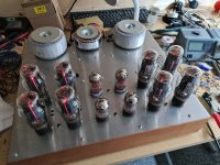
DIY M60 OTL Power Amplifiers
I actually have more recent pictures as these are now mine - and I believe Kim actually cleaned up the last bit's of the circuit so they are now straight as an arrow. Admirable work
I am using mine in an active system, so I have been driving these with MiniDSP 2x4HD, 4x10HD and latest they are on the SHD's balanced outputs
I believe that I also used the LS2BmkII at an early stage, but that was with a less than optimal load on the M60's thus hard to tell a lot about the "marriage" but expect that to work well also.
But what I really want - and is heading towards as soon as I have time (way to many projects in the pipeline) is the MP3 !
Had I been in the states I would have picked up a used one long ago! ... but they are almost as rare as hens teeth in Europe - so I will have a go at it my-self.
Actually have collected most of the parts needed already. Just need to figure out the last bit's of the design")
The M60's are going nowhere from here - they are absolute awesome!
A big thank you to you Ralph for this awesome design.
The overall layout is not far away from these
DIY M60 OTL Power Amplifiers
I actually have more recent pictures as these are now mine - and I believe Kim actually cleaned up the last bit's of the circuit so they are now straight as an arrow. Admirable work
Hi All,
With the end of the build in sight, can I ask what pre-amps people are using with their M-60's.
as transformers and cases where possible from previous projects. I'd love to try an MP-3 but again that is beyond my current budget.
Any thoughts / comments / suggestions gratefully received.
Cheers
Steve.
I am using mine in an active system, so I have been driving these with MiniDSP 2x4HD, 4x10HD and latest they are on the SHD's balanced outputs
I believe that I also used the LS2BmkII at an early stage, but that was with a less than optimal load on the M60's thus hard to tell a lot about the "marriage" but expect that to work well also.
But what I really want - and is heading towards as soon as I have time (way to many projects in the pipeline) is the MP3 !
Had I been in the states I would have picked up a used one long ago! ... but they are almost as rare as hens teeth in Europe - so I will have a go at it my-self.
Actually have collected most of the parts needed already. Just need to figure out the last bit's of the design
The M60's are going nowhere from here - they are absolute awesome!
A big thank you to you Ralph for this awesome design.
@valvemaniacuk The tricky bit is actually the power transformers used in the Circlotron. You can get electrostatic noise introduced into the output of the circuit if you aren't careful!
I have built the Alan Kimmel circlotron, and I didn't have any problem with electrostatic noise from the power supply toroids. But I did run into what I think you are talking about when I built a circlotron based on the Electro-Voice amplifier design. I had a huge problem with capacitive coupling from the floating output power supply toroids, and when I first turned it on there was an intolerable buzzing kind of hum (even before the tubes warmed up!).
I eventually figured out that I could null out the buzz almost completely, by judicious use of capacitors from the secondary windings to ground. They needed to be finely tuned in order to reach the null, and in the end I used an old variable tuning capacitor to find the ideal values, and then after measuring the capacitance, soldering in series/paralleled capacitors to achieve the required values.
The problems of capacitance coupling in the output power supply transformers in a circlotron are greatly enhanced, of course, in an amplifier like the Electro-Voice that has output audio transformers, since the impedance in the output circuit is so much higher than in an OTL circlotron.
The main problem I did notice with my Alan Kimmel based circlotron was that there could be very considerable imbalances between the quiescent currents in the paralleled output tubes. (Imbalances like a factor of two almost, between one and another.) In the end I decided not to worry about it, since there didn't seem to be much that could be done.
Last edited:
Hi All,
With the end of the build in sight, can I ask what pre-amps people are using with their M-60's.
As I have been running the Transcendent Beasts for some years, I initially used the grounded grid pre-amp, (built from a kit) and then scratch built Rozenblit's Masterpiece pre-amp after I came across the schematic for it which had been leaked onto the web.
I will, of course start with the Masterpiece, but would be interested to know if anyone else has used this combination and what they thought of it. I also have at home a (currently unpopulated) chinese clone pcb for the CAT SL1 (What looks very much like an accurate full version) and have also previously built the Lite Audio LS26 chinese cheapy version which worked suprisingly well, once a few errors in the schematic were rectified. So the SL1 will also be built up at some stage and I will be interested to see how that works with the M-60's. Happy to look at other pre-amps, but budget will be limited so realistically it will be a home built unit so I can re-cycle parts such as transformers and cases where possible from previous projects. I'd love to try an MP-3 but again that is beyond my current budget.
Any thoughts / comments / suggestions gratefully received.
Cheers
Steve.
I'm using a modified Schiit Freya for my pre-amp. It has balanced outputs.
I have built the Alan Kimmel circlotron, and I didn't have any problem with electrostatic noise from the power supply toroids. But I did run into what I think you are talking about when I built a circlotron based on the Electro-Voice amplifier design. I had a huge problem with capacitive coupling from the floating output power supply toroids, and when I first turned it on there was an intolerable buzzing kind of hum (even before the tubes warmed up!).
I eventually figured out that I could null out the buzz almost completely, by judicious use of capacitors from the secondary windings to ground. They needed to be finely tuned in order to reach the null, and in the end I used an old variable tuning capacitor to find the ideal values, and then after measuring the capacitance, soldering in series/paralleled capacitors to achieve the required values.
The problems of capacitance coupling in the output power supply transformers in a circlotron are greatly enhanced, of course, in an amplifier like the Electro-Voice that has output audio transformers, since the impedance in the output circuit is so much higher than in an OTL circlotron.
The main problem I did notice with my Alan Kimmel based circlotron was that there could be very considerable imbalances between the quiescent currents in the paralleled output tubes. (Imbalances like a factor of two almost, between one and another.) In the end I decided not to worry about it, since there didn't seem to be much that could be done.
Do you have an illustration of your capacitor network scheme or some ballpark values for the compensation? I’m interested in this in the event that I run into this issue.
I figure for my Kimmel knockoff I will have to do some sort of rudimentary tube binning to try and minimize quiescent differences. I suppose some mismatch among tubes won’t terribly effect the sound at the end of the day.
New preamp thread
Hi Norgaard,
They are superb looking amplifiers. Very impressive.
Have now started a new thread for a pre-amp based on the MP-3. Hopefully you will be willing to contribute your thoughts and ideas
New thread here -
Differential preamp based on the Atma-sphere MP-3
Cheers
Steve.
But what I really want - and is heading towards as soon as I have time (way to many projects in the pipeline) is the MP3 !
Had I been in the states I would have picked up a used one long ago! ... but they are almost as rare as hens teeth in Europe - so I will have a go at it my-self.
Actually have collected most of the parts needed already. Just need to figure out the last bit's of the design
Hi Norgaard,
They are superb looking amplifiers. Very impressive.
Have now started a new thread for a pre-amp based on the MP-3. Hopefully you will be willing to contribute your thoughts and ideas
New thread here -
Differential preamp based on the Atma-sphere MP-3
Cheers
Steve.
Do you have an illustration of your capacitor network scheme or some ballpark values for the compensation? I’m interested in this in the event that I run into this issue.
I figure for my Kimmel knockoff I will have to do some sort of rudimentary tube binning to try and minimize quiescent differences. I suppose some mismatch among tubes won’t terribly effect the sound at the end of the day.
I just took a look under the chassis of my Electro-Voice style circlotron. It was a couple of years ago that I built it, and I had forgotten what a bird's nest of compensating capacitors I ended up with! Essentially, it really comes down to two capacitors for each channel. One capacitor from an end of the power-transformer secondary of the upper power supply to the negative DC output of the lower power supply, and the other capacitor from an end of the power-transformer secondary of the lower power supply to the negative DC output of the upper supply. In each case, the bird's nest is because I needed a lot of series/parallel capacitors in order to hit just the right value using what I had available. I think the net capacitance was of the order of 500pF or so, for each of the two.
As I mentioned, I used a variable capacitor first to optimise the nulling, and then strung together capacitors to get the right values. Getting them close was quite critical for really quieting the buzz. And it was a multi-step process, especially since I had only one variable capacitor available. So I would first optimise the buzz reduction for the first capacitor, and then replace it with a fixed combination capacitor to hit the measured value. Then optimise the buzz reduction on the second capacitor. Then, go back and re-optimise for the first capacitor. And so on...
I don't think it would make much difference, as far as the buzz cancellation was concerned, whether the two capacitors were connected at one end to the negative DC or the positive DC of the other power supply. But from a convenience and safety point of view, it was much better to have the frame of the variable capacitor at the potential of the negative DC output (which is close to ground), rather than the positive DC output (which is something like 420V in the Electro-Voice)!
But, as I said, I think this was really only necessary because this is a circlotron with audio output transformers. This means the impedance in the output is something like 1600 ohms, rather than the 8 ohms or so of an OTL circlotron. This makes the effects of capacitive coupling from the power transformers hugely more troublesome than in an OTL circlotron.
Essentially, it really comes down to two capacitors for each channel. One capacitor from an end of the power-transformer secondary of the upper power supply to the negative DC output of the lower power supply, and the other capacitor from an end of the power-transformer secondary of the lower power supply to the negative DC output of the upper supply. In each case, the bird's nest is because I needed a lot of series/parallel capacitors in order to hit just the right value using what I had available. I think the net capacitance was of the order of 500pF or so, for each of the two.
So if I’m picturing this correctly, the capacitor network forms an “x” connecting the AC of one floating power supply to the DC of the other and vice versa? Interesting concept, will have to look into this a bit more.
But, as I said, I think this was really only necessary because this is a circlotron with audio output transformers. This means the impedance in the output is something like 1600 ohms, rather than the 8 ohms or so of an OTL circlotron. This makes the effects of capacitive coupling from the power transformers hugely more troublesome than in an OTL circlotron.
True, probably not applicable to my OTL although I had looked into the possibility of an OPT circlotron topology during my initial project brainstorming. Might come in handy yet someday. Thanks for breaking it down for me!
current hogging with paralleled tubes of very high transconductance is the issue with such tubes, so cathode resistors are used, you can use higher valued resistors and then capacitor bypass them so as not to reduce tranconductance.
i know that tubes like the 6c33, 6336, 7242 are prone to this issue of current hogging, but for tv scanning tubes, i am not so sure, perhaps the tube gurus will chime in...
sorting tubes by cathode currents can be costly too, unless you get the for a dollar each and you have lots of them...
i know that tubes like the 6c33, 6336, 7242 are prone to this issue of current hogging, but for tv scanning tubes, i am not so sure, perhaps the tube gurus will chime in...
sorting tubes by cathode currents can be costly too, unless you get the for a dollar each and you have lots of them...
current hogging with paralleled tubes of very high transconductance is the issue with such tubes, so cathode resistors are used, you can use higher valued resistors and then capacitor bypass them so as not to reduce tranconductance.
i know that tubes like the 6c33, 6336, 7242 are prone to this issue of current hogging, but for tv scanning tubes, i am not so sure, perhaps the tube gurus will chime in...
You mean like this? It's also possible to run a separate line for the feedback. It doesn't matter too much which tube (ecc99 here) but these are kept in siloed pairs.

I did that just for solving the variation of tube tuning!
So if I’m picturing this correctly, the capacitor network forms an “x” connecting the AC of one floating power supply to the DC of the other and vice versa? Interesting concept, will have to look into this a bit more.
Yes, precisely. I assume this is achieving a nulling out of the effects caused by the capacitive coupling of primary to secondary in the toroidal power transformers.
Well, after a few delays, amp No.2 is now alive and pre-conditioning the output tubes. Amp No.1 is now ready for having the HT wired up, having spent a week with just the filament supply connected, so will hopefully get that on the test bench this weekend. So if all goes well, it's music time next weekend
Cheers,
Steve.
Cheers,
Steve.
Attachments
Ooops, forgot to ask.
Will be putting fuses in the +ve rails for each output stage. What value is recommended? I assume they should be slow blow types.
Thanks.
Steve.
I would not fuse the rails of the output section! If one fails but not the other the amp can push DC.
Instead fuse the primary of the B+ transformer. Depending on how much capacitance is present you might be able to use a fast blow fuse. But generally we use a 3A slow blow.
You mean like this? It's also possible to run a separate line for the feedback. It doesn't matter too much which tube (ecc99 here) but these are kept in siloed pairs.
View attachment 943989
I did that just for solving the variation of tube tuning!
you can not have current hogging with just a single tube, it has to be two or more tubes in parallel....
but bias runaway with single tubes is also possible......
you can not have current hogging with just a single tube, it has to be two or more tubes in parallel....
but bias runaway with single tubes is also possible......
Agreed. That PP stage has 4 of those stages (4 tubes) for class A operation as a small headphone amp with a CCS for each pair plus the danger becomes the output caps. I remember Broskie’s making a point about cathode resistors (10-30R) for the 6as7 being needed for stability.
Last edited:
Amp No.1 is working
Have now got the first amp up and running. Measuring around 17V RMS at the onset of clipping, so getting around 40W out of the amp which I am happy with. All appears to be OK. Easily managed to zero the dc on the output, and there is very little variation once it has settled down.
One thing that I have noticed is that the frequency response starts to roll off above 10kHz. I am assuming it should extend significantly beyond this, so can some-one point me in the right direction to look at what may be causing it.
Apart from that all looks really good. The tubes measure up reasonably consistently in terms of quiescent current at idle. Voltages across the 5 ohm cathode resistors are generally between 0.25 and 0.3V so we've got 50 - 60mA running through the tubes.
Looking forward to getting the 2nd one running and listening to some music.
Cheers,
Steve.
Oscillation issue?
OK, have looked into the frequency response issue a little further and it is actually starting to fall off around 3 - 4kHz. I have also noticed that I am getting a distinct whistling from the amp at that frequency, which I believe would suggest I'm getting some oscillation somewhere. I am not seeing anything on the oscilloscope trace, however, so whatever is happening is not affecting the signal output.
Just leaving it to cool down a little and I'll check through the wiring again to see if I've made any errors, but any suggestions as to the cause would be gratefully received.
Cheers,
Steve.
- Home
- Amplifiers
- Tubes / Valves
- What tubes for a OTL tube amp?