Pics please!
I am working at the M60 project, collected most of the components. I am now designining the cabinet layout, 90% done.
Would like to see pics of yours, please!
I also have a question about the tube heaters. I am going to use three different transformers whith 25Vac secondary and will connect four tubes in series, so two transformers for the two groups of power tubes, plus one for the signal tubes, but not sure is good to power all the four 6sn7 together, because they are at very different potential. Is it better to use two separate windings? And maybe refer them to different potential? Like in SRPP circuits?
Thanks!
Giuliano
@Bambini,
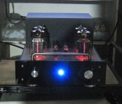
This should be similar to the m60 Amp.
Best regards, Frank
Thanks for posting this. I always wondered what their design looked like.
Hi All,
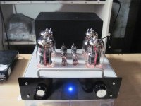
Almost ready to start the M-60 build. As mentioned in a previous thread, am using the chassis I built a pair of Transcendent Beasts in some time ago. The pcb's and output circuitry of these amps have gone to a new home. Still missing some key parts, but got plenty of bits already, and planning on spending some time over Easter with the soldering iron
Will post a few pictures on the forum as I go.
Cheers,
Steve.
Attachments
Switch on thump
Another quick question if I may -
Most of the valve (tube) designs that I have built have had their power supplies configured so that the power to the heaters is applied at the same time as the HT to the anode, usually with a thermister in circuit to minimise in-rush current to the transformers. Whist I appreciate that this is not necessarily ideal for the tubes, it does ensure that the amp fires up quietly.
If I was to configure the supply so we had a 'standby' switch, and an 'operate' switch as drawn, would I expect to hear a pop, bang or other cone wilting noises through the speaker as the HT is applied to the tubes with the heaters already on and working.
Thanks.
Steve.
I have built several OTLs, and apart from the first one I have never bothered with arranging a delayed HT switch-on. When I re-jig my original one I am going to remove the delayed turn-on, among other changes. I think I had been unduly influenced by some discussions about the "dangers of cathode stripping" when I was building it, and I would certainly never include a delayed HT again. OTLs must be just about the least susceptible of any amplifiers to cathode-stripping, since the HT voltages are so low (typically 150V or so).
The OTL I did build that has a delayed HT makes only a very slight thump when the HT comes on. So it appears to be harmless, but pointless, I would say. It was a bit nerve-wracking the first time I fired up the amplifier, waiting to see what would happen when the HT turned on!
I used to delay B+ with a time delay relay. 10 seconds or so using NE555 DC 12V Delay Relay shield Timer Switch Adjustable Module 0 To 10 Second | eBay driving a 40A automotive relay.
Now I don't bother although a new build I'm doing for a client will use a relay to control B+ from C- supply. That way if there's a bias supply failure, the tubes won't be destroyed.
The biasing module also supports "Open collector" error output, but I have no idea how to use it (I assume you use an NPN transistor, emitter to ground, collector to the relay, base to "TTL error" output, but I don't really know). I'm guessing if there's an error, the output will go to ground, turning off the transistor. I think it's just easier to use a relay on the supply")
Now I don't bother although a new build I'm doing for a client will use a relay to control B+ from C- supply. That way if there's a bias supply failure, the tubes won't be destroyed.
The biasing module also supports "Open collector" error output, but I have no idea how to use it (I assume you use an NPN transistor, emitter to ground, collector to the relay, base to "TTL error" output, but I don't really know). I'm guessing if there's an error, the output will go to ground, turning off the transistor. I think it's just easier to use a relay on the supply
Last edited:
A
Most of the valve (tube) designs that I have built have had their power supplies configured so that the power to the heaters is applied at the same time as the HT to the anode, usually with a thermister in circuit to minimise in-rush current to the transformers. Whist I appreciate that this is not necessarily ideal for the tubes, it does ensure that the amp fires up quietly.
If I was to configure the supply so we had a 'standby' switch, and an 'operate' switch as drawn, would I expect to hear a pop, bang or other cone wilting noises through the speaker as the HT is applied to the tubes with the heaters already on and working.
Thanks.
Steve.
That is why the M-60 (and all of our amps) are built with a standby switch.
In my amps I always power the filaments for 30-60seconds before applying B+. Sometimes I do this with a 555 based delay circuit and relay and other times I just use two power switches and count to at least 30.
I've only ever had the very gentlest of noise when B+ is applied.
I've only ever had the very gentlest of noise when B+ is applied.
Amp No.1 progress
Hi All,
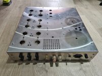
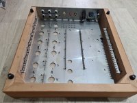
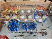
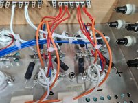
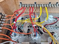
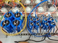
Thanks for the comments and feedback. A few photos attached of the build of the 1st amp. Output stages and power supplies now almost complete. Just the driver stages and then the fitting of the transformers and we should be almost ready to go. The predicted Siberian weather that we are expecting in the UK tomorrow should give me a good excuse to lock myself in the cave and get this first amp finished off.
Hi All,
Thanks for the comments and feedback. A few photos attached of the build of the 1st amp. Output stages and power supplies now almost complete. Just the driver stages and then the fitting of the transformers and we should be almost ready to go. The predicted Siberian weather that we are expecting in the UK tomorrow should give me a good excuse to lock myself in the cave and get this first amp finished off.
Attachments
- Home
- Amplifiers
- Tubes / Valves
- What tubes for a OTL tube amp?