djk said:"Such a MOSFET driving use of LM4702 might be very possible."
Only rated to drive 5mA out, and no more than 6V output differential (cannot drive MOSFETs).
ok.
so now we know this.
thanks, djk
yeah,
even if I had hope it could drive FastEddy mosfets,
and so also be more useful to All Them
MOSlim FETamentalists:
THE FET Maffia

... LM4702 was most probably designed only with BJT Power transistors in mind
- like those big darlingtons used in that 100watt amplifier application note
Here is a picture of that 100 watt beefy looking thing:
Attachments
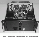
Lineup: Great picture = tells it all.
Just wondering if you have had experience with switching power supplies for better quality amps, etc.
My thoughts were to take the amp, mount it flat in the bottom of a low profile case ( http://www.chip-pcb.cn/images/47023.gif ) and add a low profile SWPS ( http://www.coldamp.com/opencms/opencms/coldamp/en/productos/sps80/index.html?idioma= ) and put it all into a 1U rack mount case. (1.75" tall, absolute max.) What say you?
I had a look at those switch power supply modules.
They have regulated voltage output.
This is about the only advantage I can see.
It keep a steady voltage across amplifier at various output.
You should ask them in Class-D forum, or maybe in Power Supply forum.
They would know much more than I do.
I really prefer usual Transformer.
Does not even matter if is the old E-type or Those round Toroid.
I take whatever I can get in the bigger sizes, often from Surplus Material sales.
I own a rather new Harman-Khardon 2x100 watt integrated amplfier.
With remote control and everything.
It uses one very big and heavy E-Type trafo.
Placed right in center of the amplifier box.
There have been a ton of posts in the chipamp forum about the LM4702, and there have been a couple of rounds of boards ordered through this forum. Most of the chip guys (meaning me! ) don't really know/haven't had the experience of designing good output stages. What has been used so far are pretty simple, but there is a ton of interest in getting a scalable, discrete output stage put together for these chips. The LM4702's themselves are incredibly easy to implement, so the weak link is now the output stage. There was a thread started a while back about this very subject and at the time it received very little interest. Is now the time to revive it?
) don't really know/haven't had the experience of designing good output stages. What has been used so far are pretty simple, but there is a ton of interest in getting a scalable, discrete output stage put together for these chips. The LM4702's themselves are incredibly easy to implement, so the weak link is now the output stage. There was a thread started a while back about this very subject and at the time it received very little interest. Is now the time to revive it?dfdye: " ... The LM4702's themselves are incredibly easy to implement, so the weak link is now the output stage. ..."
Well, there is also room for improvement in the input stage. It appears that the LM4702x would lend itself to balanced inputs quite nicely ( + & -, inverting / noninverting inputs just like a lot of op-amps) ... if anyone spots a circuit to do this, please advise,
Well, there is also room for improvement in the input stage. It appears that the LM4702x would lend itself to balanced inputs quite nicely ( + & -, inverting / noninverting inputs just like a lot of op-amps) ... if anyone spots a circuit to do this, please advise,
"a scalable, discrete output stage "
Just use the triple EF output stage (Leach). The LM4702 is rated at only 3mA (minimum output), a double EF is borderline for current gain.
Each pair of outputs (use MJ21193/94) will be good for about 100W.
One pair on ±42V, 100W/4R.
Two pair on ±52V, 200W/4R.
Three pair on ±63V, 300W/4R.
Four pair on ±75V, 400W/4R.
Five pair on ±85V, 500W/4R.
Six pair on ±95V, 600W/4R.
Ten pair on ±95V, 1KW/2R.
Hi,
a triple EF may run out of voltage to drive 6 Vbe + 2 Vre, with only 6v available between the source and sink.
A triple could be made to work if the Vbe of each stage is reduced by minimising bias currents and similarly Vre can be reduced if device matching allows 0r1 or 0r15 emitter resistors. Then loadings down to 2ohm are achievable.
A dual EF with hFE of 100 (driver) and 50 (output) gives 15Apk from 3mA (spec minimum). 4r * 15Apk delivers 60Vpk and is equivalent to 450W into 4ohm (4pair of MJ21193/4 or MJL4301/4281- from your table would probably be about right).
4pair would require a gain of 50 @ 3.8Apk which is achievable. Slightly higher driver gain would allow for a little more gain droop into a nominal minimum impedance (3r) for a real 4ohm speaker.
8ohm speakers are no problem.
I cant understand one thing.
Such a BIG Power chip
and only drive like max ~5mA
What I have a slight memory of
from some topic here in forum is that
the most current that needs to be cooled, by that big package
is the SUPPLY current for the LM4702 circuit itself.
And of course, as it has got option to use 200 volt
this means power and heat. Power = volt x current.
But still, as it looks to have about same package, case, capsule
as LM3875 and LM3886 ( 68 Watt output )
I would really have expected more output current than a few milliampere.
-----------------------------------
LM4702B ±20V to ±100V
LM4702C ±20V to ±75V
Equivalent Noise 3µV
PSRR 110dB (typ)
General Description
The LM4702 is a high fidelity
audio power amplifier driver
designed for demanding consumer
and pro-audio applications.
-----------------------------------------------------
I am, myself, more interested in the 2x75 watt variant, LM4702C.
Because already
2x65 volt peak = 264 Watt RMS into 8 Ohm
2x65 volt peak = 528 Watt RMS into 4 Ohm
And I never think more than max 50-100 Watt and I try get some quality instead.
Anybody know if there are any QUALITATIVE differences
between the lower voltage LM4702C and 2x100 volt version LM4702B ?
lineup
Hi Line,
Nat have issued an updated datasheet.
They show the specs for the B & C grades.
A few of the spec seem to show tighter tolerances for the B grade.
Nat call the C grade the mass market version.
Using the maximum 30mA quiescent current and +-100Vdc then dissipation is 6W.
Using a 10C/W sink and Rth c-s = 1C/W the Tc will be about 66Cdegrees above ambient.
This could give junction temperatures of around 110 to 130 degreesC when fitted inside an amplifier.
I expect the 3mA to 5mA output limits to be ClassA and probably single ended.
Nat state that the quiescent is fixed, but Glen? has found that the chip ground lead has a dirty return current implying something other than pure ClassA inside.
LM4702 Audio Power Amplifier Driver
.
Have a look at this website:
LM4702 Audio Power Amplifier Driver
plenty plenty of good info about LM4702 and how to use it
among all info at ....
Glenn Baddeley - Audio and Hi-Fi (australia) http://www.werple.net.au/~gnb/audio/
.... one link to this diy project (actually to a diyaudio.com member site!)
LM4702 prototype with Sanken SAP16P and SAP16N
DIY Amplifiers -- The LM4702 meets Sanken SAP16
My lineup comment:
Sanken makes high class transistors.
Many of which are excellent for use in Audio Power Amplifier.
For example wellknown: 2SC2922 + 2SA1216 !!!!
lineup
.
Have a look at this website:
LM4702 Audio Power Amplifier Driver
plenty plenty of good info about LM4702 and how to use it
among all info at ....
Glenn Baddeley - Audio and Hi-Fi (australia) http://www.werple.net.au/~gnb/audio/
.... one link to this diy project (actually to a diyaudio.com member site!)
In 2005 National Semiconductor introduced the LM4702 device driver.
This chip provides the input and drive functions
for either bipolar junction transistors, or MOSFET's.
....................................
I chose instead to use the Sanken SAP16N and SAP16P power Darlingtons which were obtained from Profusion in the U.K.
Profusion got the transistors to me in just a few days with their webstore and Royal Mail.
Importantly, the Sanken devices with their built in temperature sensing diodes make it unnecessary to use a Vbe multiplier to prevent thermal runaway.
An externally hosted image should be here but it was not working when we last tested it.
LM4702 prototype with Sanken SAP16P and SAP16N
DIY Amplifiers -- The LM4702 meets Sanken SAP16
My lineup comment:
Sanken makes high class transistors.
Many of which are excellent for use in Audio Power Amplifier.
For example wellknown: 2SC2922 + 2SA1216 !!!!
lineup
Lineup & AndrewT"
L " ... Such a BIG Power chip and only drive like max ~5mA ..."
A " ... using the maximum 30mA quiescent current and +-100Vdc then dissipation is 6W ..."
L " ... of course, as it has got option to use 200 volt this means power and heat. ..."
L " ... chip ground lead has a dirty return current implying something other than pure ClassA inside ... "
From link(s) below: " ... Do I need a heat sink for the LM4702?
You do not need a heat sink on the LM4702 itself. However, it is necessary to use a heat sink on the output stage. The LM4702 does have internal thermal protection, but this does not monitor the output stage. ..."
I'm speculating a little bit here: National would, of course, like to build a "one size fits all" type of power amp / pre-amp input stage chip and I bet there are plenty of mass market manufacturing customers who will want it that way (for reduced inventory headaches, etc.). The "BIG" heat sink (as AndrewT points out) is certainly needed for those cases of very significant rail voltage and power output, ~=> +/- 50 VDC or more, and if (as most manufacturers will probably want to do) there is one single power supply for a whole mass market production device (for cost savings, low parts count), then mounting the die on a extra "BIG" heat sink will fulfill the requirement. Additionally, the manufacturers will also want a common heat sink for the '4702 and any output drivers, and that "BIG" heat sink tab will thermaly stablize (and thermaly lock) the input parts and output parts together = more accurate voltage following and better over all specs like THD, popcorn noise rejection, CMRR, etc.
Good eyes, Lineup: This is very interesting: http://www.werple.net.au/~gnb/audio/lm4702.html >> " ... At 10 Volts RMS output, THD+N is about 0.005% across a 20 Hz to 20 KHz bandwidth. ... It steadily drops to about 0.0015% at maximum output voltage. ..." (It would seem that there is a decimal place error: /=/ 0.015% ?) " ... At very low output voltages the data sheet shows that THD+N rises to over 0.1% ..." (this is more likely National's reality than the author's).
Interesting design & build suggestions all over this web page like: http://www.werple.net.au/~gnb/audio/images/4702GndPinConn2d30.jpg (& http://www.werple.net.au/~gnb/audio/images/4702GndCurrent1b10.jpg ), http://www.werple.net.au/~gnb/audio/images/4702Heatsinking1e20.jpg ... setting the "mute function": http://www.werple.net.au/~gnb/audio/images/4702MuteResistor1d5.jpg
So, best advise to DIY designers using the /4702: use a common heat sink for this chip and the output drivers, if possible, and pay close attention to your star ground scenarios.
Thanks should be given to Glenn Baddeley (glennb) for the research and web pages above. This page had been hit 5000+ times so there is a lot of interest in this chip besides us here at DIYAudio ...
(Should we start a new thread or update and otherwise follow through on these LM4702 DIY pages? ... I still want balanced inputs and power MOSFET outputs on mine.)
... more ...
From Lineup's second link above = http://www.tech-diy.com/Amplifiers/LM4702_Sanken.htm : " ... National recommends that you use 2 toroidal transformers and full wave bridges for the positive and negative supply rails and I won't quibble with them. ..."
National recommends?? I would have said "suggests" instead as trying to reduce CMRR (crosstalk) inside the chip, externally, is a serious mis-use of resources. Also having common ground references between the two bridge/filters of the twio supplies might lead to ground loop questions, defeating the purpose of dual supplies : http://www.tech-diy.com/Amplifiers/LM4702_Power.gif ...
Better to have seperate, isolated mono-block amp chips than multiple transformers and multiple diodes sets of two power supplies if the effort is to reduce or improve crosstalk specs. Also tying two supply sources together at the ground(s) for alternate voltage sources (for other boards & equipment?) is more easily resolved with simple linear voltage regulation (LM317, etc.) = better specs ... No?
Interesting as well: " ... he Sanken devices with their built in temperature sensing diodes make it unnecessary to use a Vbe multiplier to prevent thermal runaway. ..." Is this more justification for using a common heat sink for the '4702 and the output drivers ?
Very nice job BTW, Lineup !! A mighty fine "one off" DIY board and layout ...
FastEddy said:
Good eyes, Lineup: This is very interesting: http://www.werple.net.au/~gnb/audio/lm4702.html
----------------
Thanks should be given to Glenn Baddeley (glennb) for the research and web pages above. This page had been hit 5000+ times so there is a lot of interest in this chip besides us here at DIYAudio ...
Should we start a new thread or update and otherwise follow through on these LM4702 DIY pages?
I still want balanced inputs and power MOSFET outputs on mine.
.
I suggest you start a new LM4702 topic in Chip Amps.
something with LM4702 and Power FET in subject.
There are many many, as you know, that are interested in
New Chip Projects as well as very many Interested in MOSFET.
So this strategy might generate some posters!
The LM4702 + MOSFET twist
would add something new as complement to those several 'old' LM4702 topics.
Besides, those old topics, some of them are so long topics (many posts to read).
There are ways to use LM4702 with MOSFETs.
No doubt in my mind.
Member: jackinnj - the owner of http://www.tech-diy.com/ sure would know.
He might have tried Lateral MOSFET and they could possibly be used,
if not the IRFXXXX HEXFET can be used.
If you find this better,
you could hang on at some other LM4702 topic,
I have seen at least ONE new topic about LM4702 in 'Chip Amps'
and several new posts in older LM4702 topics. With images of builds.
I myself has got many other things to focus at, for now.
But I may jump in again,
if I think I have any useful idea or comment.
About LM4702 - an interesting and intriguing Chip
>Solid State>Chip Amps>something with LM4702 and Power FET
Like this? http://www.diyaudio.com/forums/showthread.php?postid=1081741#post1081741
Like this? http://www.diyaudio.com/forums/showthread.php?postid=1081741#post1081741
Have you checked this thread? Towards pg 4 or pg 5 'veteran' uses and is quite happy with output Fets with the 4702.
http://www.diyaudio.com/forums/showthread.php?s=&threadid=79322
http://www.diyaudio.com/forums/showthread.php?s=&threadid=79322
Hi all. Relatively new member here. I know this is an old thread, but is the LM4702 chip still a good module to build a 100wpc amp around? I'm getting ready to build a 'audio grade' amp and want to pick the best all-around chipamp for doing this. I may also consider some of the DIY choices for class D modules too.
I'm reading a lot here on DIYAudio and appreciate everyone's take and experience on the topic. I am confused a bit on whether or not you need to use additional transistors (as in Darlington pair) to get the level of output I want, or can you just use the module? Perhaps more reading is necessary. I've seen some cool Class D amps on eBay that look intriguing. I'm an expert at using a soldering pencil and have put numerous kits together. Even DIY'd a few amps over the years.
Thots?
redjr
LM4702 chip good module to build a 100wpc amp around?
sure is : http://www.ti.com/lit/an/snaa045/snaa045.pdf (with 2 pairs per channel)
Last edited:
- Status
- This old topic is closed. If you want to reopen this topic, contact a moderator using the "Report Post" button.
- Home
- Amplifiers
- Solid State
- what poweramp is realy the best to build?