well i must say im busted. LOL
i figured that since i had a good preamp board and that i have gone over the burnt preamp board and replaced everything. i thought it would make noise with either one of them. no sir im busted!! i know you told me earlier to do it and i just didnt listen. it seems to work wonderfully now with those jumpers in place.
so now i start on the preamp boards? i have gone over the board several times replacing as much as i could see that has failed. i see there is another 072c op amp here can i check and replace it the same as the other one?
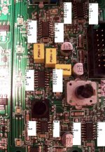
I only have one photo of part of the preamp board. It shows at least 2 open resistors. Did you replace them?
If so, you need to confirm that you have positive and negative 15v on the power supply pins of the op-amps. Do this for ALL op-amps on the preamp board.
Did you replace all of the TL074s on the preamp board?
If so, you need to confirm that you have positive and negative 15v on the power supply pins of the op-amps. Do this for ALL op-amps on the preamp board.
Did you replace all of the TL074s on the preamp board?
If you measured the voltage correctly, the op-amp is almost certainly defective. Sometimes op-amps will not act as you'd expect when the output is driven to the rail (as this one is) so there's a slim chance it's OK. Replace the resistor (assuming it's defective) and measure the voltage again.
Did you plug this board into the main board at any time when the regulators were producing too much output?
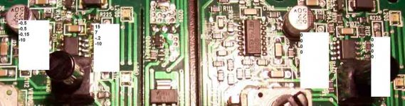
The one with all zeros has open 10 ohm resistors.
Did you plug this board into the main board at any time when the regulators were producing too much output?
The one with all zeros has open 10 ohm resistors.
i found 9 defective 10r0 resistors, actually every single one was defective. i plugged power to it and i still dont have +-15 v on the 072c. should i change it now or keep digging first?
the larger IC's TL074c's are these op amps too? i have 2 of 4 that are getting signifigantly hot. should i check them similarly to the little 072? look for +-15v on the corners?
after i put power to this board i was concerned that there might be a chance to blow up some of my newly replaced transistors. is this valid? should i be using resisted power still?
im only going to be working on the cooked board first because the other one seems to be a good referance for me. but a quick look at the good one and it looks like most/all the 10 ohm resitors are open.
You need to find the 10 ohm resistor in series with pin 4 of the 072. It's likely defective. If it's not, the op-amp may be dragging the voltage down. If that's the case, change the 072.
The TL072 is a 2 channel op-amp. The TL074 is a 4 channel op-amp. The power pins on the 074s are the center pins on each row.
There is a chance that the preamp board could damage the regulators. I doubt that the current limiting resistor would prevent that. If you don't use the current limiting resistor, use a 10-15 amp fuse.
If all of the resistors were open, there's a good chance that all of the op-amps have been damaged.
i am having trouble with this little board. is there a way to check if the op amp is good or bad before changing it? i have changed all of them and 2 of them are getting hot. i changed the 2 again and they are still getting hot. all 4 of these op amps have +-15v on the center leg and the 072c has +-15v on the corners. i changed all the 10 ohm resistors and all were bad.
is it possible to remove all 5 opamps then apply power to the board? would it stand to reason that there should be no sound and nothing getting warm?
if i replace all op amps and all 10 ohm resistors should it be working?
is it possible to remove all 5 opamps then apply power to the board? would it stand to reason that there should be no sound and nothing getting warm?
if i replace all op amps and all 10 ohm resistors should it be working?
When an op-amp is being used for audio, the inverting and non-inverting inputs will be within 0.010v (typically). If they are not and the rest of the circuit is intact, the op-amp is generally defective. If you're not sure, post the voltage on all of the pins. Copy and past the following for each op-amp.
IC#
Pin 1:
Pin 2:
Pin 3:
Pin 4:
Pin 5:
Pin 6:
Pin 7:
Pin 8:
Pin 9:
Pin 10:
Pin 11:
Pin 12:
Pin 13:
Pin 14:
Don't pull the op-amps yet.
The 10 ohm resistors are OK if the op-amps have ±15 on them. The voltage on the op-amps will tell us if they are working properly or not. .
IC#
Pin 1:
Pin 2:
Pin 3:
Pin 4:
Pin 5:
Pin 6:
Pin 7:
Pin 8:
Pin 9:
Pin 10:
Pin 11:
Pin 12:
Pin 13:
Pin 14:
Don't pull the op-amps yet.
The 10 ohm resistors are OK if the op-amps have ±15 on them. The voltage on the op-amps will tell us if they are working properly or not. .
It looks like you may have lost a ground.
With the amp off and your meter set to ohms, find the SMD electrolytic capacitor terminals that are connected (0 ohms - 10 ohms) to the ±15v (power supply) pins of the op-amps. Are the opposite terminals of those capacitors connected to the chassis ground terminal of the amplifier?
The preamp board will have to be plugged into the main board. There may be more than two capacitors connected to the ±15v supplies.
Ignore the previous post.
The 3 op-amps nearest the controls for the display are for the LEDs. The voltages there are not important for audio.
If you don't have a tone generator or a test tone CD, download and burn the following file to a CD or your signal source of choice.
http://www.bcae1.com/temp/100hz300seconds.zip
Drive the signal (100Hz sine wave) into the amplifier. Set the level to 0.50v AC (black lead on shield, red lead on center conductor of RCA jack - inside amplifier).
The gain button should be set to 10x. The gain, crossover and bass boost should be set to the center position.
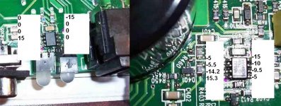
These are the voltages on the various op-amps. The black meter lead will be connected to the chassis ground terminal for the following measurements.
On the main board...
Op-amp near RCAs
Pin 1: 0.205v
Pin 7: 0.205v
On the preamp board...
Op-amp nearest the black connector:
Pin 1: 0.205
Pin 7: 0.205
Pin 8: 0.209
Pin 14: 0.080
8 pin op-amp:
Pin 1: 0.055v
Pin 7: 0.148v
Op-amp near the center of the board:
Pin 1: 0.106
Pin 7: 0.314
Pin 8: 0.316
Pin 14: 0.313
Your amp should be within ~10% of the voltages above.
The 3 op-amps nearest the controls for the display are for the LEDs. The voltages there are not important for audio.
If you don't have a tone generator or a test tone CD, download and burn the following file to a CD or your signal source of choice.
http://www.bcae1.com/temp/100hz300seconds.zip
Drive the signal (100Hz sine wave) into the amplifier. Set the level to 0.50v AC (black lead on shield, red lead on center conductor of RCA jack - inside amplifier).
The gain button should be set to 10x. The gain, crossover and bass boost should be set to the center position.
These are the voltages on the various op-amps. The black meter lead will be connected to the chassis ground terminal for the following measurements.
On the main board...
Op-amp near RCAs
Pin 1: 0.205v
Pin 7: 0.205v
On the preamp board...
Op-amp nearest the black connector:
Pin 1: 0.205
Pin 7: 0.205
Pin 8: 0.209
Pin 14: 0.080
8 pin op-amp:
Pin 1: 0.055v
Pin 7: 0.148v
Op-amp near the center of the board:
Pin 1: 0.106
Pin 7: 0.314
Pin 8: 0.316
Pin 14: 0.313
Your amp should be within ~10% of the voltages above.
i know i have been gone fow a long time but im back and im more excited then ever to finish these repairs
i have enclosed a picture of the op-amps. i put the sin wave on my computer and put it on re-play. i managaed to get .497 AC volts so very close.
none of these op amps seem to be doing anything. the legs seem to either be +-15v or else 0.
also at location D301 and D302 there are 2 little LED that are lighting up. i didnt notice these before and i wonder if they are important for anything.
Attachments
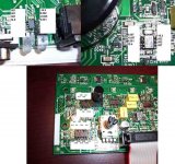
Those LEDs generally only light up when DC is applied to the input (as when you drive the input with the speaker level signal from a head unit).
Your meter was set to DC volts. You wouldn't see any voltage on the other terminals of the op-amps if your meter was set to DC.
The DC voltages you read seem normal.
Your meter was set to DC volts. You wouldn't see any voltage on the other terminals of the op-amps if your meter was set to DC.
The DC voltages you read seem normal.
- Status
- This old topic is closed. If you want to reopen this topic, contact a moderator using the "Report Post" button.
- Home
- General Interest
- Car Audio
- what is this?