Perhaps the sound was dominated by the input transformer?The best sound I got from LM3886 is with gain of 2.8. You need 1W 180ohm Rf and 1/2W 100ohm Rg. No DC blocking capacitor. To get perfect square wave I need to add 22pF-50pF // to Rf.
The simulator shows this character.
I use 600-10k transformer ($25 for pair) as input gain.
s is complex frequency. You can view it as a way to cover the amplitude response and the phase response in one variable. Or see Laplace transforms.Question is, what does “s” means in the above formula?
Yep. As I wrote in Post #7, you need to make sure that the gain at ~800 kHz is 20 dB. Or at least that's one solution. You can also aim for a rate of closure around 20 dB/dec. The central point is that you need to have good phase margin and gain margin if you want good stability.I’m reading more on stability and discovered that I can use the gain of, say 5x, but only if I implement proper lead/lag compensation . It is shown in data sheet as RC network over the feedback resistor.
As I wrote in Post #9, Chapter 8 of Franco is a good place to start: https://archive.org/details/SFrancoDesignWithOperationalAmplifiersAndAnalogIntegratedCircuits1Pdf
Tom

You should be safe in most cases with gain 10xI am in the process of a project converting some speakers to active and will power them with LM3886. The preamp/active crossover is complete but I have too much gain in that stage for the current sensitivity of my LM 3886 implementation which is standard datasheet stuff (gain around 20x). Am I safe to reduce this to 10x or will I encounter stability issues. Thanks. Martin
I did some simulations with LM3886.
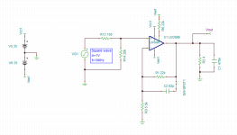
Here is the circuit using Gain=5.
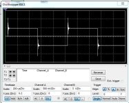
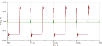
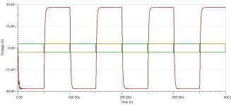
Then 2 oscilloscope images.
First is without compensation cap across the feedback resistor.
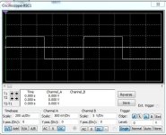
Second is with a capacitor 82pF across fb resistor.
At gain=5 this cap was necessary to make perfect squarewave.
Not more not less capacitance.

Here is the circuit using Gain=5.
Then 2 oscilloscope images.
First is without compensation cap across the feedback resistor.
Second is with a capacitor 82pF across fb resistor.
At gain=5 this cap was necessary to make perfect squarewave.
Not more not less capacitance.
Attachments
I did some simulations with LM3886.
Here is the circuit using Gain=5.
Then 2 oscilloscope images.
First is without compensation cap across the feedback resistor.
Second is with a capacitor 82pF across fb resistor.
At gain=5 this cap was necessary to make perfect squarewave.
Not more not less capacitance.
View attachment 1250999
What simulator software are you using?
I tried 82pF cap but it oscillates.
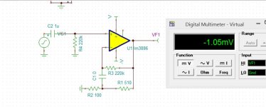
My schematics is missing input decoupling cap, output Thiele, and Zobel networks.
I also loaded 0.47uF cap over the output 4R resistor.
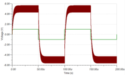
Attached are schematics and square wave.
Attachments
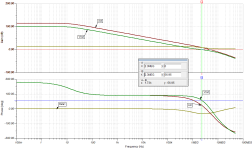
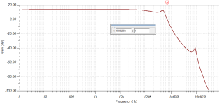
So the compensation is called feedback lead compensation.
It allows for the phase to lead ahead by certain margin.
Can see from the graph attached.
Aol curve is phase response without compensation.
Vout is the new phase response.
From reading on theory little bit, such compensation allows for lower bandwidth, and hence lower noise.
It allows for the phase to lead ahead by certain margin.
Can see from the graph attached.
Aol curve is phase response without compensation.
Vout is the new phase response.
From reading on theory little bit, such compensation allows for lower bandwidth, and hence lower noise.
Attachments
Last edited:
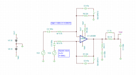
I realized that I needed to use capacitor as a load and it should've been without resistor in parallel.
I also added decoupling capacitors to the inputs as well as output Thiele/Zobel networks.
Finally getting proper simulation.
Adding two 47pF caps seems to be lowering loop gain to stabilize the whole circuit. Adding two 33pF is on the edge of instability.
This is a difference amp topology to be used with balanced inputs.
Attachments
That is interesting way to do a feedback.
220,000/100 = 2,200x gain if capacitor is not accounted for.
That is 66dB of gain limiting over the whole frequency range.
Adding cap of 1uF in conjunction with 220k creates filter with fc=0.72Hz.
180R resistor is then "loosens/dampens" the filter.
Am I understanding correctly?
So is 1uF cap acting as lead compensation sort of?
And then adding another lead comp cap to 180R?
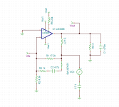
At DC the capacitor, C1, is an open circuit, so you have unity gain through R3.
Above some corner frequency (where C1 is a short circuit) the gain is 1+(R3 || R1)/R2. As R3 >> R1 this can be approximated as 1+R1/R2 or 2.8 V/V with the values shown.
That's definitely too low for the LM3886, which is why a compensation cap across R1 is needed to ensure good phase margin.
I've come across this type of feedback arrangement before in some older discrete designs (Hitachi? Toshiba? I forget). I suppose it's a relic from the times where electrolytic capacitors had pretty horrid audio performance. With the scheme shown in Post #33 relatively low feedback current flows in C1, so it will have only a tiny impact on the audio performance of the circuit.
With the more traditional approach with C1 in series with R2 (which requires a much larger C1) the full feedback current flows through the capacitor so its impact on the audio performance is much larger.
The main issue with the approach shown in Post #33 is that if C1 blows or dries out (thereby going open circuit) the LM3886 will not have any DC feedback path and will output the full rail voltage onto the speaker. That said, with C1 = 1 uF one could use a film cap or ceramic cap. It'll outlast any of us in that application.
Tom
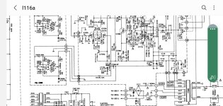
Of course, it is the Duo-β feedback network from Luxman many moons ago.I've come across this type of feedback arrangement before in some older discrete designs (Hitachi? Toshiba? I forget).
Do you remember on which model Luxman or at least, the decade that was used?
Google gives me Luxman l116 to be duo beta and here is the circuit. It has the tone control in the feedback.
Google gives me Luxman l116 to be duo beta and here is the circuit. It has the tone control in the feedback.
Attachments
Last edited:
Engineering College of Copenhagen, University of Washington followed by over a decade at National Semiconductor and Texas Instruments combined. Why?Where did you study electrical engineering?
Tom
- Home
- Amplifiers
- Chip Amps
- What gain is safe to use for LM3886?