Hi,
There is absolutely nothing about the above arrangement that is
good for low bass, 20Hz with authority is a complete pipe dream.
rgds, sreten.
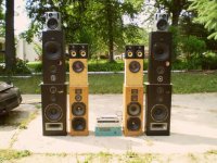
It's a W-frame dipole.
Even when dipole losses are accounted for, the 6x15" woofers (there are, after all, 3 of these cabinets) will probably produce 20Hz just fine.
Seems a bit wasteful to me - those drivers could do far more in a proper cabinet - but the size of each 2x15" cab isn't to be sniffed at either.
Chris
Where the amplifier aspect really comes into the equation is that the power supplies on these are often pretty marginal, they sag and ripple ferociously when asked to do serious work, and you then combine that with amplifier circuitry which has very poor rejection of that ripple; no wonder tight bass can be difficult to achieve, it just comes out rather soggy ...
So, easy solutions: extremely efficient speakers so the amp is barely out of first gear, or separate amplifier to handle all the bass spectrum, so that the floppy power supply of the amp handling the rest of the spectrum can do a decent job ...
Frank
So, easy solutions: extremely efficient speakers so the amp is barely out of first gear, or separate amplifier to handle all the bass spectrum, so that the floppy power supply of the amp handling the rest of the spectrum can do a decent job ...
Frank
Appropriate damping for the speaker being driven. An amplifier can have too much damping and you end up with lean bass.
I'm sure I'm guilty of this as well!
So, to make amends, here's a posting from last November made on another forum.
(I wrote: )
AK's Dave Newman (dnewma04) wrote:
"Let's do some math.
We know that damping factor is a ratio, specifically, it's the load impedance divided by the output impedance of the amplifier. For now, we'll ignore how amplifiers attain low output impedance just for the sake of simplicity.
So, let's say we have an amplifier with a damping factor of 2000 and an impedance of 8 ohms.
DF = Load Impedance / Output Impedance
2000 = 8 / Output Impedance
Output Impedance = .004
All is well in the world, right? We have our staggeringly high damping factor but we've ignored something important.
We forgot to include the series resistance of the speaker wire between the amp and speakers. Let's redo the calculation now.
Again, we know that DF = Load Impedance / Output Impedance, but now we are going to add in the effects of the speaker wire into our equation to figure out what the "real" or "effective" damping factor is of the real world situation. For simplicity sake, we'll err on the side of caution and say that it's very low resistance wire and only presents a .1 ohm load.
DF = 8 ohm / (.004 ohm + .100 ohm)
DF= 8 ohm / .104
DF= 76.9
The advertised damping factor of 2000 is now only 77 at the terminals of the speakers.
Now, let's look at what is going on at the terminals of the woofer in a speaker system with a passive crossover.
It's not unusual to have a series resistance of 1 ohm in a passive crossover, but just for a best case scenario, let's say that it's only .25 ohm.
DF = 8 / (.004 + .100 + .250)
DF = 8 / (.354)
DF = 22.6 at the woofer.
Now, let's say the damping factor of the amp is 20000! Surely that must make a huge difference being an order of magnitude higher than 2000!
Unfortunately, the reality is:
DF = 8 / (.0004 + .25 + .1)
DF = 22.8
It's essentially the same.
Now, let's say that the amplifier in the same scenario is only at 50.
DF = 8 / Output impedance
50 = 8 / Output Impedance
Output Impedance = .16
Now that we have the output impedance of the amp with a DF of 50, let's substitute into our scenario to see the DF at the woofer:
DF = 8 / (.16 + 1 + .25)
DF = 8 / (.51)
DF = 15.7
Do you see how most people just don't find DF that important? In the real world, the difference between a low DF amp and a ridiculously high DF amp is essentially moot at the woofer."
Best Regards,
TerryO
If damping is too high for a particular speaker even after the speaker wire, small series resistance can be added to reduce output Z as seen by the speaker. It is not as easy to decrease Zout by such a simple modification. Sort of like in cooking, you can always add salt but it is not so as easy to take it away.
") An amplifier output node that acts more like an ideal voltage source for a wide bandwidth is rather enticing.
An amplifier output node that acts more like an ideal voltage source for a wide bandwidth is rather enticing. If damping is too high for a particular speaker even after the speaker wire, small series resistance can be added to reduce output Z as seen by the speaker. It is not as easy to decrease Zout by such a simple modification. Sort of like in cooking, you can always add salt but it is not so as easy to take it away.
Adding series resistance has always (for many years) been an option. I know that GM and more recently, Nelson Pass have mentioned added resistance, etc., for better bass from SS amplifiers.
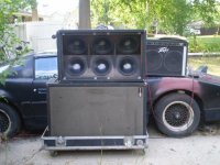
i think i know what the OP is looking for. when i was a teenager i went to an outdoor concert by a local rock band at our high school. the bass player had a literal wall of EV or JBL bass bins, and the effect was astounding, especially outdoors and at a distance of over 100 feet away, you could feel the "thump". if i remember correctly there were at least 6 dual 15" bass bin cabinets arranged 3 wide and 2 high. for 12 15" woofers, that would be about 15sq-ft of woofer surface area driving 72 sq-ft of horn coupled surface area at the front of the bass bins. it may sound "old school", but those big bass bins really had some punch to them. especially with a SS amp with at least a resonably high DF.
Last edited:

Exactly what you mean by "iron fist" bass I am not sure but whatever it is, (I suspect it's punch region enhancement), the amplifier really has not got much to do with it but the speakers do.
The usual thing is to have a q=2 peak at around 60 Hz. this has been the standard sort of thing used for 40 years that I know of, in all sorts of disco d.j. and live band situations, and most of the common "pro" drivers you get are optimised for it, at one time w horn boxes were used but these have gone out of fashion.
rcw
I agree that the psu will be pretty marginal in many amps. I have seen decent bass only in the systems which has large psu. I have thought this factor into consideration.
In terms of ripple current Im considering to build the psu in such a way that the amount of current each BJT demands I would be considering to have that much ripple current from the psu capacitors. Example: If there are 4 output devices can give 10Amps output then I would be taking 4 caps with each has ripple not less 10 amps and the psu having equivalent current capability. I wanted things to be very rugged. Even the Psu filter capacitors that would be Industrial grade.
In terms of ripple current Im considering to build the psu in such a way that the amount of current each BJT demands I would be considering to have that much ripple current from the psu capacitors. Example: If there are 4 output devices can give 10Amps output then I would be taking 4 caps with each has ripple not less 10 amps and the psu having equivalent current capability. I wanted things to be very rugged. Even the Psu filter capacitors that would be Industrial grade.
I love that damping factor saga of getting reduced so I believe there are very few factors which results in good bass. If im not wrong they would be either ability of the psu or number of output devices or feedback type.
I have searched for the crown amp schematic couldnt get the reference one... If anybody has it can u post it.
I have searched for the crown amp schematic couldnt get the reference one... If anybody has it can u post it.
Looking at this from a different perspective, what amp and PSU do you need to get the best bass you can from the speaker you are using?
Although you may never achieve the bass you crave with the speakers you have, there are ways to make what you have sound better. Let's see if folks here can help.
Although you may never achieve the bass you crave with the speakers you have, there are ways to make what you have sound better. Let's see if folks here can help.
I love that damping factor saga of getting reduced so I believe there are very few factors which results in good bass. If im not wrong they would be either ability of the psu or number of output devices or feedback type.
Whether damping factor means anything is really a chicken-or-egg phenomenon. Amps with power supplies that can take you hand off if you're not careful, and have 3x the number of outputs that they "need", and use buss bar wiring tend to have high damping factors. Ones that skimp by on a couple of 2200 uf caps, one pair of Jap outputs, skinny pcb traces and 22 ga. wiring tend to have lower damping factors. Equalize the two by putting a 0.2 ohm resistor in series with the monster amp and it will STILL trash the other in the bass department. It's not the damping factor itself - it's the design features that tend to result in a low DF. You can build an amp with a cheap undersized supply that has a DF of 5000 by moving the feedback takeoff point to right at the speaker terminal and adding another stage inside the feedback. You'll take on more problems than you'll want to deal with, and it won't help the bass a bit.
When using low Qt high efficiency drivers, current feedback to increase the output impedance is quite often used.
I well remember when the whole damping factor thing first became prominent, that was when solid state amplifiers with no output transformers became available.
In order to sell them the marketers latched upon the high damping factor of these and since then this has been raised to the status of holy writ, and it is true that it did somewhat restrain some of the more boomy reflex boxes that were around at the time.
All you need to do is put output series resistance in win isd of .01 and then .1-.5, these are the sort of numbers people quibble about and if you do it you can see that it makes no difference at all, put 10 Ohms and you get a peak and this is what most d.j. disco systems are after, the good old bass punch peak.
rcw
Even when dipole losses are accounted for, the 6x15" woofers (there are, after all, 3 of these cabinets) will probably produce 20Hz just fine.
Actually there are just two cabinets. The box is a cardioid loaded dipole with a front compression chamber. The math was vetted by John K who has done considerable theoretical and real world work on this sort of containment. They are tuned to room load with back side damping thickness and measured for in room extension. To me, with peak spl at 110 db, a 20 Hz signal at 80 db is "with authority".
Don't be too harsh on sretin, wouldn't matter what I brought to the table, it would cause a direct vent to his spleen. Plenty of other folks in the same predicament.
As for amplifier power supplies, get rid of the tera-farad of capacitance. Order a power transformer that will provide peak load values as if they were RMS and do so with less than 3% loss, no load to full load. You can do this with an EI core transformer that is designed for guitar amp work and built like an audio transformer or with a Toroid. Both will provide what you need for sustained low bass and everything else on top of that.
Modern power transformers are designed to provide only capacitor fill, with nothing left over for transient situations. Capacitors are fine for ripple suppression, but for anything but a regulated power supply without non linear draw, they really are not enough. And really, I don't care about what numbers might prove otherwise. I can guarantee that if you get a stout enough power transformer and shed excess capacitance, you will never look back.
Bud
hi BudP yeah i agree the ruggedness of the psu is been ignored by many people. Im not talking of the psu capacitors only but the trafo.
I have a big question lurking in my mind for quite some time. I can source the toroidal transformer with regulation of 5% max but I always thought of losses in the trafo but somehow I feel that the transients are connected to the loss factor in the trafo. What exactly is the connection in that.
Like one of my friend made a trafo for me with a rating of 400VA with 14-0-14 ratings EI type and guess it weighs 22lb absolute the core size is like 2 inch x 3.5 inch and it measures 4 inch x 4 inch x 4 inch proper cube altogether. He is a very very serious audiophile and said when it comes to psu there he doesnt want anybody to touch it since almost all manufacturers have some sort of compromise on the psu.
now the point is that there is considerable loss in the psu. So how far this is connected to the transients?
Can I take a 1.5 times the trafo size with bit more loss factor will it affect the transients?
Just for a 100RMS into 8 ohms x 2 I dont want to hesitate to use 1200VA trafo if required or
I can go with much bigger cores for toroidal trafo I can contact the toroidal manufac companies and get custom version with bigger core since losses will be very small.
If its just power loss I dont mind getting bigger trafo but if its transient loss there is something that i need to get custom built.
Transients are to do with the energy stored in the capacitors.
Since a Watt is a Joule second and the energy stored in a capacitor is cV to use the energy stored in a capacitor the Voltage across it must decrease.
If the power transformer is big enough then all the capacitors are doing is acting as filters and you can save a lot of money and space by using a capacitance multiplier, this increases the filtering effect of capacitors withought increasing the energy storage.
rcw
- Status
- This old topic is closed. If you want to reopen this topic, contact a moderator using the "Report Post" button.
- Home
- Amplifiers
- Solid State
- what factors will give iron fist bass?