It's the non-linear's that do the real damage ...This non-linear effect is not included in the simple Gootee woofer model.
Is that what I saw in my measurements? It doesn't seem like it, but could be. Maybe the low modulates the high a little more on a single cable.
SY, no I didn't do the parallel cable thing. I was just looking for a difference between 2 wires and 4 wires going to the speaker. FWIW, I saw nothing in the midrange or bass, just the tweeter.
SY, no I didn't do the parallel cable thing. I was just looking for a difference between 2 wires and 4 wires going to the speaker. FWIW, I saw nothing in the midrange or bass, just the tweeter.
Gents.
A is LF, B is HF.
The power lost in the monowire is (A+B)2R.
That is A2R plus B2R plus 2ABR.
The power lost in the biwire is A2R plus B2R.
The time integrated loss is identical for each case.
The instantaneous loss is not.
The assumption that monowire and biwire are identical violates the conservation of energy.
Do the test I recommended.
jn
A is LF, B is HF.
The power lost in the monowire is (A+B)2R.
That is A2R plus B2R plus 2ABR.
The power lost in the biwire is A2R plus B2R.
The time integrated loss is identical for each case.
The instantaneous loss is not.
The assumption that monowire and biwire are identical violates the conservation of energy.
yupThe attachment pulled from Gootee postings clearly shows that the differences in tweeter response follow the woofer current trend.
That is very important with single drivers and within the crossover area. The magnetic field of the voice coil moving in the gap creates eddy currents in the gap. The resultant inductance and resistance of the voice coil is velocity modulated.I'm considering magnetic field linearity
Is that what I saw in my measurements? It doesn't seem like it, but could be. Maybe the low modulates the high a little more on a single cable..
Do the test I recommended.
jn
Last edited:
Can't find it. Was it series resistance?Do the test I recommended.
I tend to wonder about counter-current dynamically altering the permeability of magnets on *other* drivers - effectively weakening the motor's field.
This certainly happens to most drivers within their own operation.
..and it makes me wonder if a woofer futz's with a mid. or tweeter's motor - making VC position on those drivers a little more "lossy" on a dynamic basis.
Still, I'm not a sure well separated (passive) crossover and bi-wiring would make a difference even if there was a problem (in this respect).
The plots in post#241 are supposed to show the response on the amplifier side of the cables right?
They are showing > 50dB response deviations.
Back in Post#213 you plotted what I think is the same parameters and only showed ~ 1dB response deviations.
What am I missing?
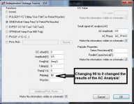
Well that is turning out to be an odd one. The single voltage source that I was using had also been used for time-domain ("transient") simulations, and so it had a sine wave set up, for that, on the left side of the voltage source setup window. But the "AC Analysis" supposedly uses the "AC Amplitude" and "AC Phase" fields on the right side of the box, in the "Small Signal AC Analysis" section, right?!
Well, somehow, changing the phase angle in the transient sine wave field from 90 to 0 caused the output to change, for the AC Analysis! Setting it back to 90 gave the same result as before. (But I think they're both wrong, since the gain ought to be around 41.5 dBv, I think.)
I am investigating. For example, the output level varies wildly as Phi is changed from 0 to 2 degrees. And with and without only an 8 ohm R load it's wildly different. Some change I made must have caused something pathological in my schematic. It's late and I have to go to bed now but I will post the LT-Spice files tomorrow evening.
I was using LT-Spice version 4.19i, dated July 2013. I synced to 4.19u and got no change in that behavior.
Attachments
Gents.
A is LF, B is HF.
Important to note that for crossovers with a less-than-infinite slope, A and B are overlapping, not distinct.
It might be helpful to consider two special cases:
1. A and B are distinct, that is, each is fully in the passband of its load and fully outside the passband of the other branch's load.
2. A and B fall right at the crossover point and are equal at each driver.
Well that is turning out to be an odd one... But I think they're both wrong, since the gain ought to be around 41.5 dBv, I think...
I was using LT-Spice version 4.19i, dated July 2013. I synced to 4.19u and got no change in that behavior.
I hear the ghost of Bob Pease rattling around.
My apologies for verbal only. The computer with the schematics is DOA, I await the new one. They were posted on AH 8 years ago IIRC..Can't find it. Was it series resistance?
1. Use one amplifier channel to drive a biwire setup and a monowire setup. This removes any possibility that the amplifier voltage output could be a factor in difference.
2. Use resistors for all tweeter and woofer loads. This removes any possibility of driver/enclosure/reflection interaction from the measurement.
3. Using single tone signals, make sure that there is indeed a null in difference between tweeter signals. Stay well above the crossover frequency. Null must be both resistor match and capacitor match. It is important that the system be exactly nulled at the frequencies where the two tone test occurs.
4. Watching the difference signal on a scope, bring up the low frequency content. If there is a difference within the system as a result of the monowiring dissipation difference, it will rear it's ugly head right in front of you as a modulation of the tweeter difference envelope. Actually, it will go from the null to a SAM.
Remember, the difference can be a result of simple amplitude modulation, or more importantly, a difference as a consequence of a phase shift. It will not be possible to discern the difference using one scope channel, and direct zero crossing measurement will not be very easy to control with respect to setup design as a result of parasitics.
Important to note that for crossovers with a less-than-infinite slope, A and B are overlapping, not distinct.
It might be helpful to consider two special cases:
1. A and B are distinct, that is, each is fully in the passband of its load and fully outside the passband of the other branch's load.
2. A and B fall right at the crossover point and are equal at each driver.
Do not confound the test by the selection of the two frequencies. Stick to frequencies well outside the crossover center.
jn
Last edited:
Do not confound the test by the selection of the two frequencies. Stick to frequencies well outside the crossover center.
Well, since you brought up the two signals (A and B), what am I supposed to make of this?
If A is outside of one driver's passband, current in that leg approaches zero. Likewise for B. So things reduce to the same as a single set of wires. If we put a signal (make it a single tone if you like) right into the middle of the crossover point, the currents in each leg are equal and half that for the single set of wires (charge conservation). So I'm truly not following your point.
Well, since you brought up the two signals (A and B), what am I supposed to make of this?
If A is outside of one driver's passband, current in that leg approaches zero. Likewise for B. So things reduce to the same as a single set of wires.
Exactly. So using single tones well outside the other drivers' current pull range is how to null the test setup. And as you say, one tone outside the other driver's passband is equivalent to the single set of wires.
As such, a single HF tone cannot be distinguishable between monowire and biwire. It is the introduction of the LF current in the monowire and it's modification of the wire dissipation with respect to biwire dissipation that I wish to examine. In the monowire case, the dissipation within the wires will have the additional 2ABR term, whereas the biwire will not.
It is important that the difference be viewed via analog subtraction. Given the fact that the 2ABR signal has net zero energy, I cannot say what an FFT algorithm would make of it. There is no net power in that signal. Given that technical question, I would consider a straight FFT as suspect. I do not want a zero result misconstrued as zero change if the equipment being used cannot see it. Like trying to measure an ac voltage with a dc meter... Zero does not mean no voltage.
jn
Last edited:
jn - thanks for the explanation.
I can see this as being difficult to implement, as it would require 2 perfectly matched* crossovers. One for mono-wire, the other for bi-wire. right?
*at least at the test fequencies
jn - thanks for the explanation.
I can see this as being difficult to implement, as it would require 2 perfectly matched* crossovers. One for mono-wire, the other for bi-wire. right?
*at least at the test frequencies
Meta?
Meta?
What's more appropriate to a biwire discussion that a bi-post??
Pano:
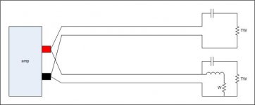
All you need are two very well matched capacitors, two well matched resistors, one lone inductor and one woofer resistor.
No need to match inductors or woof loads.
I've drawn the relevant items required. Note that for the biwire side, there is no need for a woofer load.
The top is the biwire aspect, tweeter portion only.
The bottom is the monowire.
There will be no difference between the two when the signal is tweeter only. When a LF signal is introduced, it's current will only go to the w load. If you want, you could even use DC.
If you want stronger signal, lower the w load from 8 to .5...
jn
Attachments
Last edited:
Doubling the amount of wire increases damping factor, which is a good thing from a "hi-fi" standpoint.But it does have an effect. As far as any of us can tell, a minor one. And it may not be the separate wires, just a change in wire gauge.
Doubling the wire between the amp and the crossover would be more effective from a damping factor standpoint than two separate wires going to the woofer and tweeter, which would still end up being the same damping factor as one to the crossover.
I don't know if it has been mentioned before in this thread (sorry if it has), but passive crossover components make noise at high drive levels (the music being played can be heard through the coils and capacitors themselves), as such they are to some extent transducers. Transducers are microphonic, they can pick up or transmit sound.
Bi wiring allows the passive crossover to be located outside of the speaker cabinet.
The lower sound pressure the passive crossover would be subjected to at a distance away from the cabinet would reduce any microphonic and vibrational interaction which would be greatest inside the cabinet.
Although microphonic interaction with good passive crossover components is minimal, it probably is measurable, and could be audible for those with "golden ears".
My main stereo speakers are bi wired, not for elimination of microphonic interaction (my hearing is not able to detect that problem even though I know it exists), but bi wiring allowed for fine tuning the passive crossover components (swapping capacitors and adjusting coil values) for their actual speaker room placement and my listening position.
Those changes were easily measured.
Art
Last edited:
Bi wiring allows the passive crossover to be located outside of the speaker cabinet.
You can do that with any sort of wiring.
- Status
- This old topic is closed. If you want to reopen this topic, contact a moderator using the "Report Post" button.
- Home
- Loudspeakers
- Multi-Way
- What does the crossover do differently when you bi-wire?